Micro-fabricated stamp array for depositing biologic diagnostic testing samples on bio-bindable surface

a bio-bindable surface and micro-fabricated technology, applied in the direction of chemical vapor deposition coating, positive displacement liquid engine, burettes/pipettes, etc., can solve the problems of affecting the quality of biologic diagnostic testing samples, and requiring more than one hour to complete the deposition process, etc., to achieve high precision and ease of operation configuration, low cost, and high precision

Inactive Publication Date: 2008-08-28
NATIONAL TSING HUA UNIVERSITY
View PDF12 Cites 0 Cited by
  • Summary
  • Abstract
  • Description
  • Claims
  • Application Information

AI Technical Summary

Benefits of technology

[0010]It is therefore an object of the present invention to provide new techniques including materials and method for providing a device and operation process to enable the deposition of large number of biological samples. The apparatus and method enable a parallel process of deposition and utilizing a micro-fabricated stamp array to provide a device that can be manufactured at low cost while provide high precision and ease of operation configuration. With the novel micro-stamp array manufactured by the low cost manufacturing processes disclosed by this invention, a person of ordinary skill in the art is enabled to overcome the aforementioned difficulties and limitations encountered in the prior art.

Problems solved by technology

Several technical challenging difficulties are still confronted by those who apply conventional methods and apparatuses to form micro-arrays of biological samples on a support to perform analyses of a large number of biological reagents.
The first challenge is the requirement to form a very large number of biological samples within a relatively short time to prevent over-evaporation or characteristic changes due to long time atmosphere exposure of the samples after micro array deposition.
This requirement is often a limitation when analyses are performed on micro array consisted of more then ten thousands samples.
Due to the sequential nature in dispensing a defined volume of liquid samples over the surface of a biological bindable surface, the deposition process may take more than one hour to complete even with the aid of computer controlled automation.
Several processes employed for depositing large number of biological samples in parallel experience greater degrees of random variations in sample sizes and are not very useful for practical applications.
As the following brief review will clearly illustrate that current state of the art in making arrays of biological macromolecules, such as nucleic acid or proteins, do not have sufficient technical capabilities to satisfy all these requirements.
Even with fully automatic control, this method is limited by a sequential nature of the sample dispensing processes that requires a longer period of time to complete the sample-deposition operations.
The dispensing apparatuses and the micro-range movement machine and control processor are also very expensive and require high level of design and manufacture technologies to provide such devices and control system.
And the system costs more than twenty-five thousand dollars ($25,000) for parts.
The spots deposited with this method have about 20% size variation and if used for protein spotting, the spots may lose function to due sample drying out due to the long spotting cycle.
All these methods encounter the difficulties that either the selection of sample types is limited, or having complexity on fabrication or operation processes thus become inconvenient or too expensive to be practically useful for large scale biological sample array analyses.

Method used


Image

  • Micro-fabricated stamp array for depositing biologic diagnostic testing samples on bio-bindable surface
  • Micro-fabricated stamp array for depositing biologic diagnostic testing samples on bio-bindable surface
  • Micro-fabricated stamp array for depositing biologic diagnostic testing samples on bio-bindable surface

Examples


Embodiment Construction

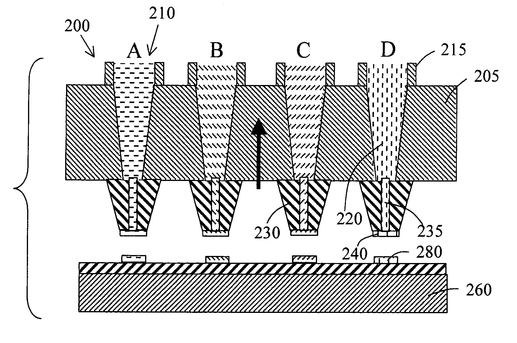
[0026]Please refer to FIG. 3A to 3C for a sequence of cross sectional views to show the basic concepts of this invention to resolved the difficulties faced by the prior art technologies. The biological-reagent deposition apparatus includes a micro-stamp array 100 formed on a silicon substrate 105. The micro-stamp array further has a great number of micro-stamps 110 formed as elongated micro-stamp-sticks extended from a front surface of the silicon substrate 105. Each of these elongated micro-stamp-sticks 110 has about a standard length that can have a range of one to few millimeters depending on applications that will be further discussed below. As shown in FIGS. 3A to 3C, these micro-stamp-sticks may be substantially elongated cylindrical stamp-sticks or may be formed as a square shaped sticks. Each of these micro-stamp-sticks 110 may have various diameters or sizes approximately few hundred micrometers (μm) to form deposition spots of different sizes depending on biological analys...


PUM

PropertyMeasurementUnit
sizesaaaaaaaaaa
diameteraaaaaaaaaa
diameteraaaaaaaaaa

Abstract

The present invention discloses micro-stamp array supported on a substrate comprising a plurality of micro-stamp sticks. Each of the micro-stamp sticks includes a micro-stamp-stick head having a channel opened through a central portion in each of the micro-stamp sticks. Each of the micro-stamp-stick heads is attached to a tapered guide tube surrounded by tapered guide-tube walls wherein the tapered guide tube is in hydraulic communication with the micro-stamp-head channel. The micro-stamp array further includes a filler chip that includes a filler reservoirs disposing on top of the tapered guide tubes, each of the filler reservoirs having a refill channel opened to the tapered guide tube for refilling the tapered guide tube and the channels.

Description

[0001]This Application is a Divisional Application of a Non-Provisional Application 09 / 892,014 filed on Jun. 25, 2001 and claims a Priority Filing Date of Jun. 25, 2000 benefited from a previously filed application 60 / 213,986.BACKGROUND OF THE INVENTION[0002]1. Field of the Invention[0003]This invention relates generally to apparatus and method for biologic reagent deposition. More particularly, this invention relates to apparatus and method for applying a micro-fabrication method for enabling high-speed deposition of large number of biologic reagent spots with low cost micro-fabricated stamps.[0004]2. Description of the Prior Art[0005]Several technical challenging difficulties are still confronted by those who apply conventional methods and apparatuses to form micro-arrays of biological samples on a support to perform analyses of a large number of biological reagents. The first challenge is the requirement to form a very large number of biological samples within a relatively short ...

Claims


Application Information

Patent Timeline
Patent Type & Authority Applications(United States)
IPC IPC(8): C40B60/14C23F1/00B05D3/00B32B37/00B01J19/00B01L3/02B81C1/00C40B40/10
CPCB01J19/0046Y10T156/10B01J2219/00382B01J2219/00527B01J2219/00585B01J2219/00596B01J2219/00605B01J2219/00612B01J2219/0063B01J2219/00637B01J2219/00641B01J2219/00659B01J2219/00677B01J2219/0072B01J2219/00725B01L3/0258B01L3/0262B82Y30/00C40B40/10C40B60/14B01J2219/00369
Inventor TSENG, FAN-GANGCHIENG, CHING-CHANG
Owner NATIONAL TSING HUA UNIVERSITY
Why Eureka
Try Eureka