Coated Microstructures and Methods of Manufacture Thereof

Inactive Publication Date: 2008-09-04
GEORGIA TECH RES CORP
View PDF47 Cites 169 Cited by
  • Summary
  • Abstract
  • Description
  • Claims
  • Application Information

AI Technical Summary

Benefits of technology

[0019]In another aspect, a microneedle device is provided for insertion of a drug into a biological tissue, which includes at least one microneedle having a base, a tip end, and a shaft portion therebetween; and a coating on at least a portion of the surface of the at least one microneedle, the coating comprising at least one drug, wherein the coating has a heterogeneous composition. The coating may include discrete particles, two or more discrete layers, two different phases, or a combination thereof.
[0020]In another aspect, a microneedle device for insertion of a drug into a biological tissue is provided which includes at least one microneedle having a base, a tip end, and a shaft portion therebetween; and a coating on at least a portion of the surface of the at least one microneedle, the coating comprising at least one drug, wherein the shaft portion of the at least one microneedle comprises one or more pockets therein. The coating may be located substantially only in the one or more pockets. The one or more pockets may contain at least a portion of the coating where the coating is in the form of a liquid, gel, microparticles, or a combination thereof.
[0021]

Problems solved by technology

These drugs are delivered almost exclusively by the parenteral route, as the oral route is generally unavailable due to poor absorption, drug degradation, and low bioavailability.
However, conventional parenteral administration with hypodermic needles undesirably requires expertise for delivery, can lead to accidental needle sticks, and causes pain, which results in reduced patient compliance.
The tough barrier posed by the skin's outer layer of stratum corneum has limited the applicability of this method to drugs that are hydrophobic, low molecular weight, and potent, as the stratum corneum's barrier properties severely limit passive delivery of most drugs, especially macromolecules and microparticles.
While the microneedle itself can be fabricated by adapting the tools of the microelectronics industry for inexpensive, mass production (Reed & Lye, Proc IEEE 92:56-75 (2004)), precise coating of microneedles presents technical challenges.
However, such dip coating to coat microneedles by simply dipping and withdrawing them from an aqueous solution of a compound (e.g., calcein, sulforhod

Method used


Image

  • Coated Microstructures and Methods of Manufacture Thereof
  • Coated Microstructures and Methods of Manufacture Thereof
  • Coated Microstructures and Methods of Manufacture Thereof

Examples


example 1

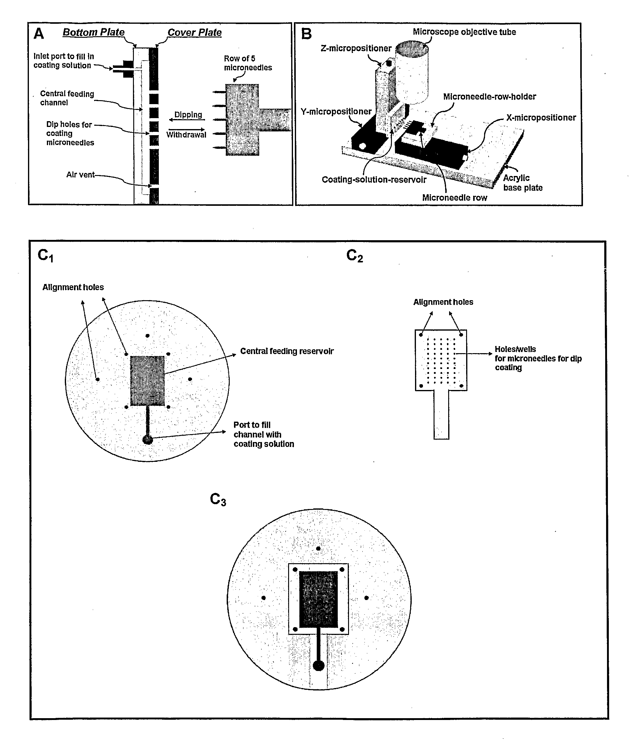
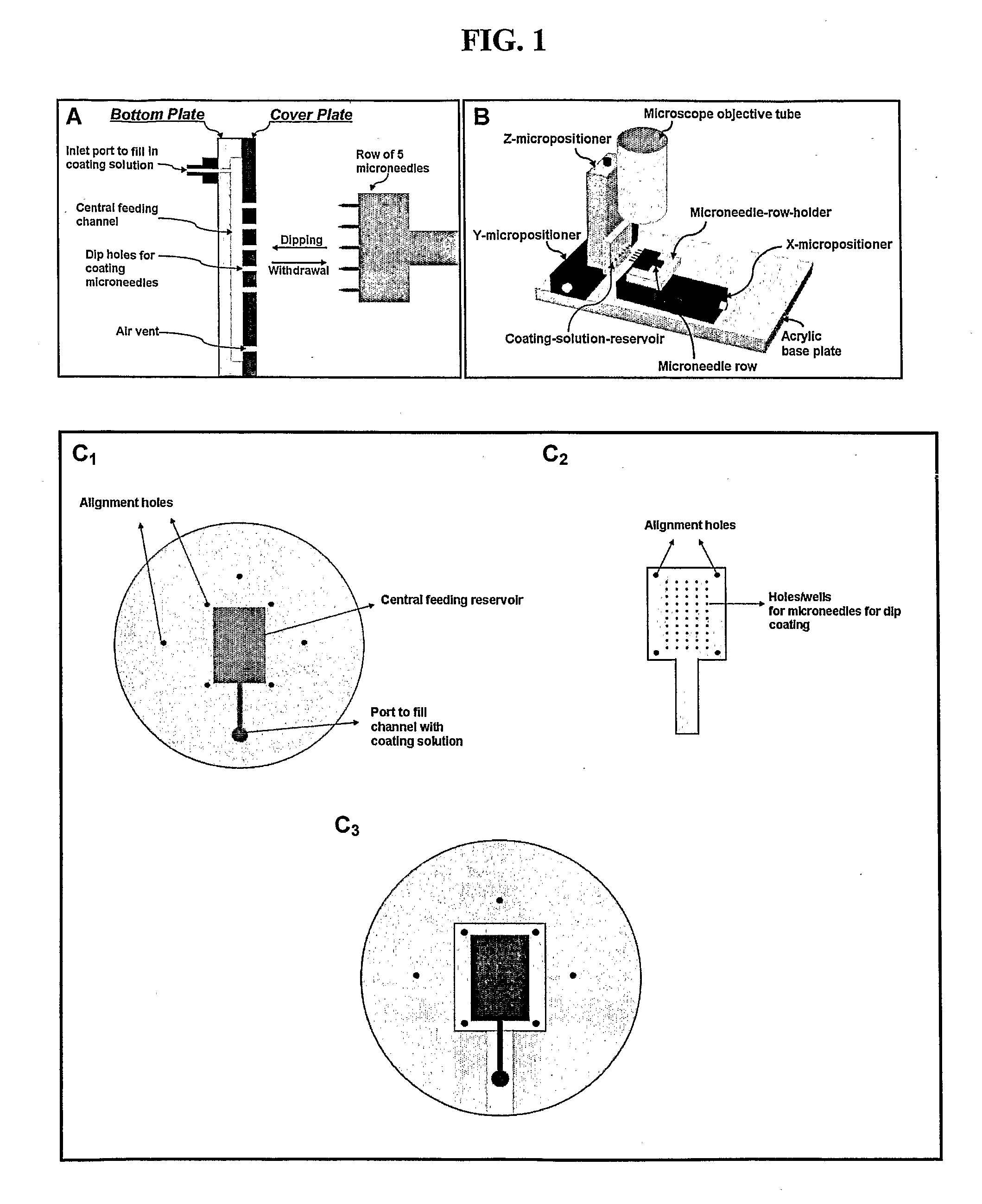
Fabrication of Coated Microneedles

[0117]Metal microneedles were laser cut, electropolished, and then coated with various coating materials. Coated single microneedles and coated microneedle arrays were produced.

[0118]Forming the Microneedle Structures

[0119]Solid microneedles were cut from stainless steel sheets (Trinity Brand Industries, SS 304, 75 μm thick; McMaster-Carr, Atlanta, Ga., USA) using an infrared laser (Resonetics Maestro, Nashua, N.H., USA), guided by CAD / CAM design, using techniques known in the art. Microneedles were prepared as single microneedles, individual rows of microneedles, or as two-dimensional arrays of microneedles.

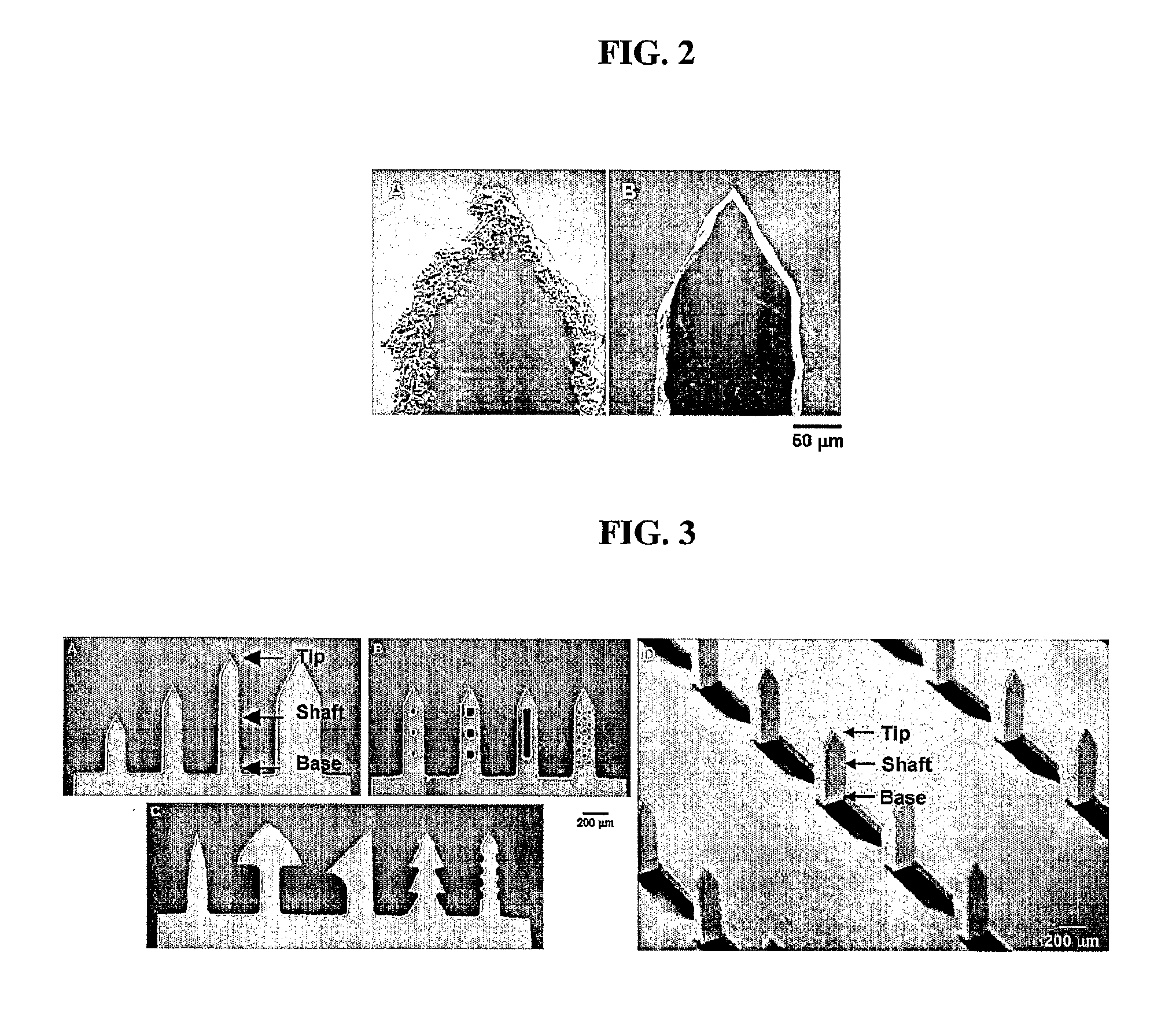
[0120]Microneedles were also made with a variety of shapes in increasingly complex geometries using laser etching. First, microneedles of different lengths and widths with a constant tip angle of 55° were created (FIG. 3A). Next, microneedles were made with small through-holes (i.e., “pockets”) of different shapes and sizes in the shafts of the ...

example 2

Assembly of Coated Microneedle Patches

[0130]Coated microneedle arrays, made as in Example 1, were assembled into transdermal patches containing pressure-sensitive adhesive to adhere to the skin. To secure microneedles in the skin at all times until ready to be removed, microneedles were integrated into a Band-Aid-like patch. This patch had pressure-sensitive adhesive on one complete side, with microneedles protruding therefrom. The adhesive secured the microneedles and compensated for the recoiling tendency of the skin and the rigid stainless steel substrate of out-of-plane microneedles. These patches were fabricated using either multiple linear rows of in-plane microneedles or individual arrays of out-of-plane microneedles.

[0131]Microneedle Patches Using Multiple Rows of Microneedles

[0132]In-plane microneedles were fabricated with a uniform adhesive layer in between the microneedles. In this example, a set of ten rows of microneedles, containing five microneedles each, was assemble...

example 3

In Vitro Dissolution of Microneedle Coating

[0135]To assess the in vitro dissolution time, single microneedles (n=3) coated with vitamin B, calcein, or sulforhodamine, made as in Example 1, were inserted into pig cadaver skin for 10 s or 20 s. Upon removal, these microneedles were imaged by fluorescence microscopy to detect residual coating. After 10 s insertion, a majority of the coating was dissolved. After 20 s insertion, the microneedle coating was completely dissolved. A sulforhodamine-coated microneedle showed similar dissolution and release into skin.


PUM


Abstract

Coated microneedle devices and methods of making such devices are provided. In one aspect, a method for coating includes providing a microstructure having at least one surface in need of coating; and applying a coating liquid, which comprises at least one drug, to the at least one surface of the microstructure, wherein the surface energy of the coating liquid is less than the surface energy of the surface of the microstructure. The coating liquid may include a viscosity enhancer and surfactant. Microneedles having heterogeneous coatings, pockets, or both are also provided.

Description

CROSS REFERENCE TO RELATED APPLICATIONS[0001]This application claims benefit of U.S. Provisional Application No. 60 / 691,857, filed Jun. 17, 2005, and U.S. Provisional Application No. 60 / 732,267, filed Nov. 11, 2005. Those applications are incorporated herein by reference in their entirety.STATEMENT REGARDING FEDERALLY SPONSORED RESEARCH OR DEVELOPMENT[0002]This invention was made with U.S. government support under Contract No. 8 RO1 EB00260-03 awarded by the National Institute of Health. The U.S. government has certain rights in the invention.BACKGROUND OF THE INVENTION[0003]This invention is generally in the field of microneedles useful in medical applications, and more particularly to coated microneedles for drug delivery and sensing, such as transdermally.[0004]Biopharmaceuticals, such as peptides, proteins, and future uses of DNA and RNA, represent a rapidly growing segment of pharmaceutical therapies (Walsh, Trends Biotechnol 23:553-58 (2005)). These drugs are delivered almost ...

Claims


Application Information

Patent Timeline
IPC IPC(8): B05D5/00A61M37/00
CPCA61K9/0021A61M2037/0053A61M2037/0046A61M37/0015A61K9/0097B05D1/32B05D5/00
Inventor GILL, HARVINDER SINGHPRAUSNITZ, MARK R.
Owner GEORGIA TECH RES CORP
Why Eureka
Try Eureka