Generation and Management of Mass Air Flow

a mass air flow and air technology, applied in the direction of electrical control, piston pumps, hybrid vehicles, etc., can solve the problems of reducing the serviceability of air charging devices, existing devices failing to provide the necessary control feedback, existing devices failing to provide sufficient mass air flow, etc., to achieve high speed, efficient power consumption, and compatibility with operating environments

Inactive Publication Date: 2008-09-11
TURBODYNE TECH INC
View PDF22 Cites 42 Cited by
  • Summary
  • Abstract
  • Description
  • Claims
  • Application Information

AI Technical Summary

Benefits of technology

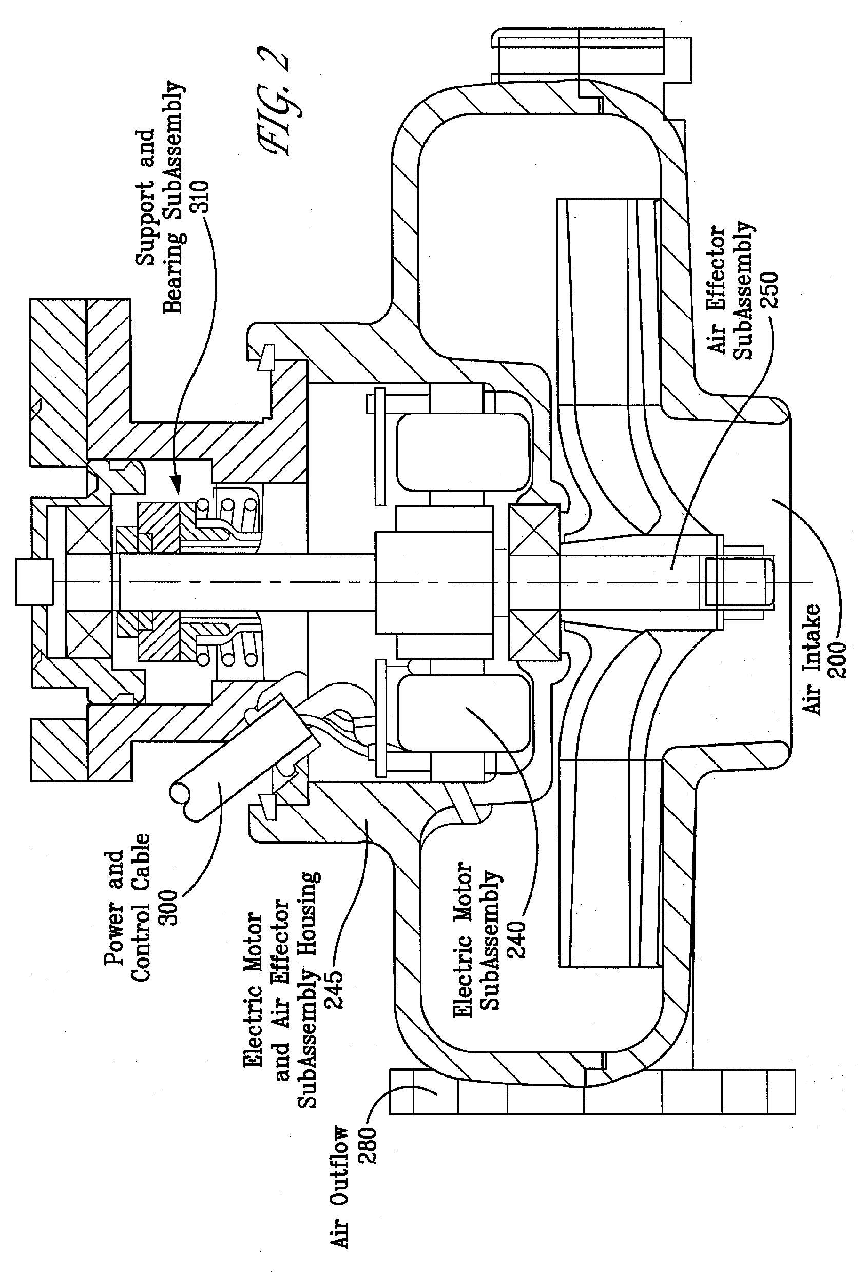
[0046]The motors used in the exemplary embodiments of the invention may be sensorless brushless direct current motors. The selection of these motors includes their advantages of high speed, efficient power consumption, and compatibility with operating environments. However, in alternate embodiments of the invention, a wide variety of motor types can be used including sensored and sensorless motors, switched reluctance, alternating current motors, brushedibrushless motors, and others that meet the needs of a specific embodiment. The selection of a motor technology and its application in embodiments of the invention may be supported by features in the control elements' use of profiles and functional isolation of the power and motor control sub-assemblies within the power elements and control elements. The selection, in an alternate embodiment, of a sensor based direct current motor may accommodate an applications' requirement of very fine shaft controls using hall-effect or optical-encoded sensors.
[0047]The motor controls used in the exemplary embodiments may be capable of starting, stopping, running, and controlling the running of motors in small increments. In an embodiment of the invention using direct current motors, the rotation of the motor may be controlled by the motor controls to the extent that discrete electrical timing pulses are handled by the motor controls to cause the sequence of electrical events rotating the shaft of the motor. This level of motor control allows the control element to support multiple speeds of rotation, different motor startup and shutdown, different energy management settings in motor operations, and different motor diagnostics. In exemplary embodiments, the power module supplying current to the motor subassembly may also contain a plurality of active (e.g., current limiters, electrical supply conditioning and filters, and others) and passive (e.g., safety interlocks against incorrect wiring, keyed connectors, and others) safety features to protect the embodiments operation.

Problems solved by technology

In many extant approaches in the known art there are shortcomings and problems with the performance of air charging devices where the resistance from existing structures, gas pressure, or resistive load degrades the ability of the air charging device to be serviceable.
1) Existing devices fail to provide a mass air flow sufficient to complete a task within the desired time window although the mass air flow over a much longer time period may be sufficient.
2) Existing devices fail to provide the necessary control feedback and use measurements to limit possible damage from an uncontrolled velocity or mass air flow.
3) Existing devices fail to provide for operation without a substantial fixed installation that generates, or stores, high pressures that can be transformed into a high velocity mass air flow.
4) Existing devices place a high load on the equipment supplying power (e.g., combustion engine, electrical feed, gas pressure, etc.) on a highly dynamic basis that causes unwanted side-effects in the system the application is supporting.
5) Existing devices place demands for space or physical configurations that cause additional costs and resource requirements beyond that desirable.
6) Existing devices fail to provide the flexibility to use high-velocity mass air flows, or slower less massive flows, to allow optimization of power expenditure, or for other purposes.
7) Existing devices fail to provide power management alternatives that allow multiple operating uses to optimally use power available in an application environment.
8) Existing devices fail to provide full coverage to handle all of the aspects of the apparatus from the low level control of the electrical motor to the connections to the entire application's apparatus structure.
9) Existing devices do not have extensive safety provisions and features to protect the device, the platform on which it is operating, or the human users.
10) Existing devices are not easily integrated into an overall platform power management and operating plan that allows flexible usage of their capabilities while managing their impact on power expenditure, instantaneous demand, and overall power capacity.
Conventional devices and applications have sought with limited success to meet one or more of these applications requirements with a wide variety of power mechanisms, air effector configurations, and control loops.
Thus, a typical fan device is inadequate for applications that require a combination of high air flow with higher pressure.
The physical diameter and consequent physical guards required also are disadvantages of conventional fan devices in even volume applications.
Also, a centrifugal air actuator may generate modest pressure, but typically requires a very large diameter blower to generate a higher pressure output.
The efficiency of other air actuator devices (such as compressors in the form of scrolls or overlapped spirals) are not as high as that of the high volume mass air flow devices described in this application.
Further, extant compressor applications tend to be specialized and constrained.
To generate pressure, a fixed compressor and tankage system (such as found in many industrial environments) may be used to provide high pressure, but the pneumatic infrastructure is substantial and the possible faults and complexity of the control systems are substantial.
But this approach reduces usable capacity of the fuel cells.
Thus, the operation of supercharger is dependent on the mechanical RPM of the engine and reduces the power available from engine at low RPM when torque is needed for acceleration or other functions.
However, these references do not disclose or teach according the inlet and outlet condition of flows full consideration in the deployment and operation of the devices.
None of these references teaches the capacity to actively incorporate active pre- and post-conditioning of the flows while managing the power and operating characteristics of the electric motor subassembly.
But these references do not disclose or teach incorporation of active inlet and outlet conditioning of flows while managing the power and operating characteristics of the electric motor assembly.
However, the teachings of these references do not support greater diversity of sensors, sensor interconnection methods, methods of utilizing sensor and sensor-based information (e.g., with direct data, or other apparatus and methods subassemblies).
These references, however, do not disclose incorporation of engine controls, other vehicular subsystems, diagnostic, comfort / entertainment, communication, or human external controls into the operation of a method and apparatus that closely operates with considerations of power modules, electric motor subassembly management, and air flows' management.
The device of this reference does not incorporate connections to sensors and control logic to manage the thermal and operating needs of the device, nor does it teach availing the apparatus of multiple sensor feeds, actively able to manage both thermal and power considerations, and the operating characteristics of an electric motor subassembly.
But these references do not teach providing a means to handle active power management with the operating characteristics of the electric motor subassembly.

Method used


Image

  • Generation and Management of Mass Air Flow
  • Generation and Management of Mass Air Flow
  • Generation and Management of Mass Air Flow

Examples


Embodiment Construction

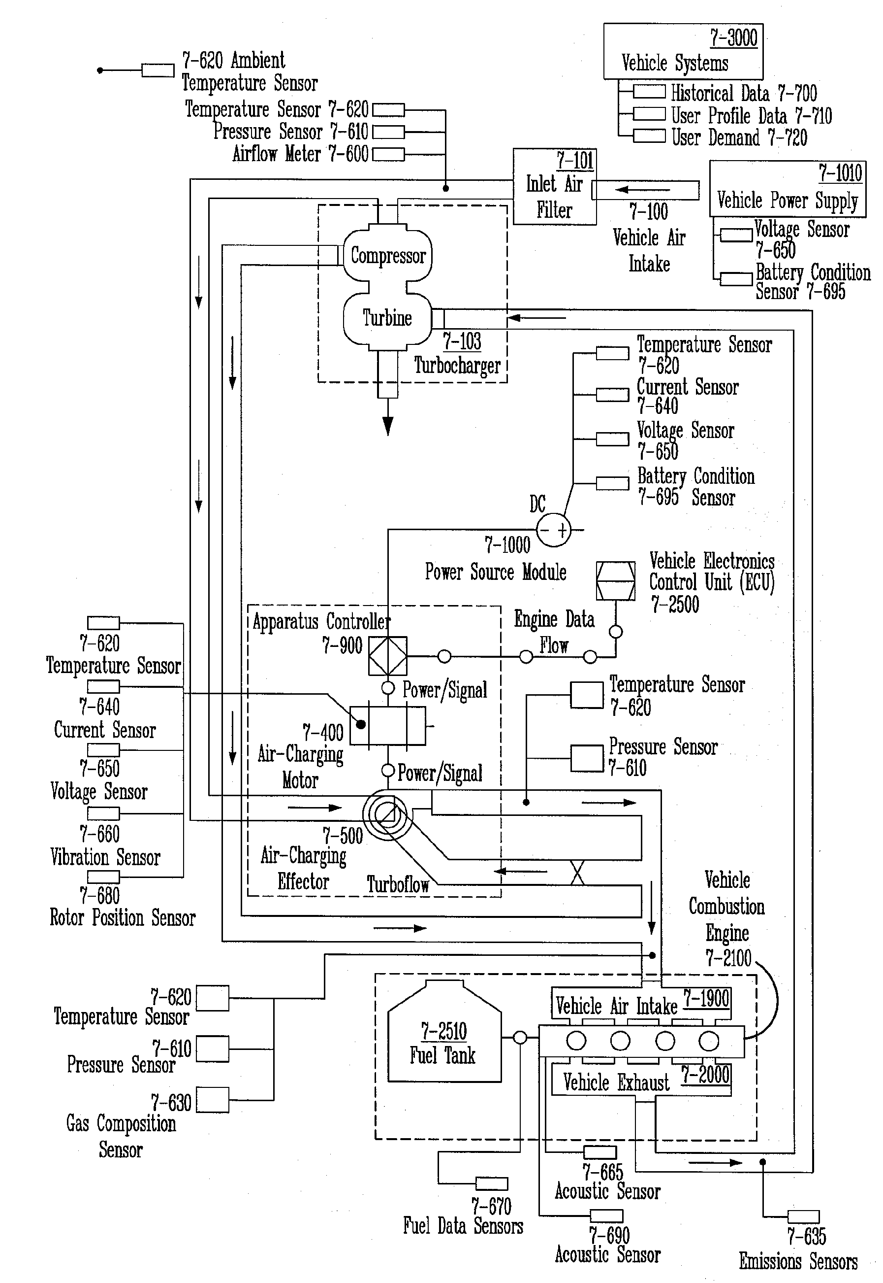
[0102]The present invention includes embodiments of systems and methods for the generation of high velocity mass air flows, or designed air flows, for use in the combustion elements of a hybrid combustion-electric vehicle.

[0103]The present invention includes embodiments of systems and methods for the generation of high velocity mass air flows, or designed air flows, for use in the combustion support elements of a hybrid combustion-electric vehicle.

[0104]The present invention also includes embodiments of systems and methods for the generation of high velocity mass air flows, or designed air flows, for use in the electrical elements of a hybrid combustion-electric vehicle for cooling applications.

[0105]The present invention also includes several exemplary embodiments of systems and methods for the generation of high velocity mass air flows, or designed air flows, for use in the electrical elements of a hybrid combustion-electric vehicle for heating applications.

[0106]Also, the present...


PUM


Abstract

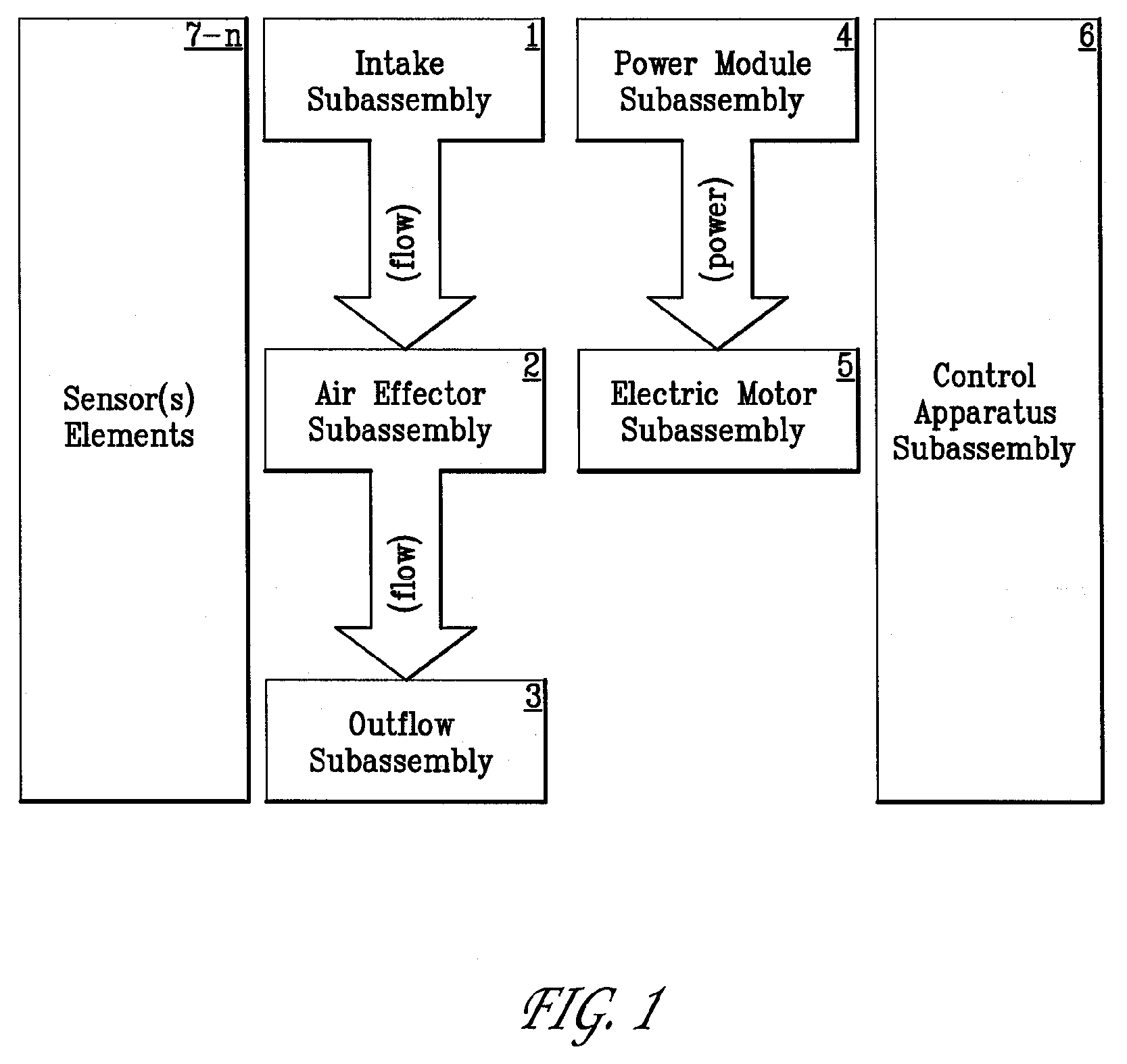
Systems and methods for generating high velocity mass air flows are disclosed. High velocity mass air flow (air charging) devices are needed in a variety of research, industrial, commercial, and consumer applications. The exemplary systems and apparatus described incorporate an electric motor subassembly, an air effector subassembly, a highly intelligent apparatus controller subassembly (and interfaces), and linked sensors, connectors, and wiring. The exemplary method described includes the operational apparatus controller subassembly (e.g., elements, logic, and behavior) that controls the entire apparatus' functions and interactions.

Description

CROSS REFERENCE TO RELATED APPLICATIONS[0001]This application claims priority to Provisional Application Ser. No. 60 / 887,424, entitled “Generation of High Velocity Mass Air Flows,” by Kwong et al., filed Jan. 31, 2007, which is incorporated herein by reference in its entirety.TECHNOLOGY FIELD[0002]The present invention generally relates to the field of air flow generation. More particularly, the present invention relates to systems and methods for generating and managing mass air flows, and subsets thereof including high velocity, high pressure, high density, and the like. This technology is particularly suited, but by no means limited, for application to hybrid vehicles, vehicles propelled by internal combustion engines, stationary applications of internal combustion engines, and ancillary uses of such air flows.BACKGROUND[0003]Applications in research, industrial, commercial and consumer applications for pressurized air flows are long standing and well known. Pneumatic systems, us...

Claims


Application Information

Patent Timeline
Patent Type & Authority Applications(United States)
IPC IPC(8): F04B17/03
CPCB60K6/46B60Y2400/435B60W10/06B60W10/08B60W20/00F01N5/04F02B33/40F02B37/007F02B37/013F02B37/04F02B37/16F02B39/10F02D23/00F02D41/0007F02D41/266F02M25/0705Y02T10/6217Y02T10/6221Y02T10/6286Y02T10/144Y02T10/42B60K6/48F02M26/03Y02T10/40Y02T10/12Y02T10/62B60W2510/0628
Inventor KWONG, ARNOLD W.MANNING, DAVID B.PRUSINSKI, THOMAS M.CASE, ALBERT F.
Owner TURBODYNE TECH INC
Why Eureka
Try Eureka