Electrode current collector and method for producing the same, electrode for battery and method for producing the same, and secondary battery

Active Publication Date: 2008-09-11
MURATA MFG CO LTD
View PDF6 Cites 3 Cited by
  • Summary
  • Abstract
  • Description
  • Claims
  • Application Information

AI Technical Summary

Benefits of technology

[0023]In the electrode for battery of according to the embodiment of the present invention, the current collector constituting the electrode for battery has the conductive layer made of crystallites having an increased grain size. Therefore, strain in the crystallites in the current collector caused due to the expansion or compression during the charging or discharging is reduced, so that the strain on the electrode for battery caused during the charge-discharge cycle is reduced, thus improving the charge-discharge cycle characteristics including the capacity retention ratio.
[0024]The electrode for battery according to the embodiment of the present invention has the structural characteristic feature obtained by the method for producing the electrode, and hence the ele

Problems solved by technology

However, even the anode electrode having the anode active material layer unified with the anode current collector formed by an improved production method poses an issue such that, as the cycle of charging and discharging is repeated, large expansion a

Method used


Image

  • Electrode current collector and method for producing the same, electrode for battery and method for producing the same, and secondary battery
  • Electrode current collector and method for producing the same, electrode for battery and method for producing the same, and secondary battery
  • Electrode current collector and method for producing the same, electrode for battery and method for producing the same, and secondary battery

Examples


first embodiment

[0045]In the present embodiment, an example is described in which an electrode current collector is formed by the method for producing an electrode current collector according to an embodiment of the present invention and a lithium-ion secondary battery is formed using as an anode electrode an electrode for battery including the above-formed electrode current collector.

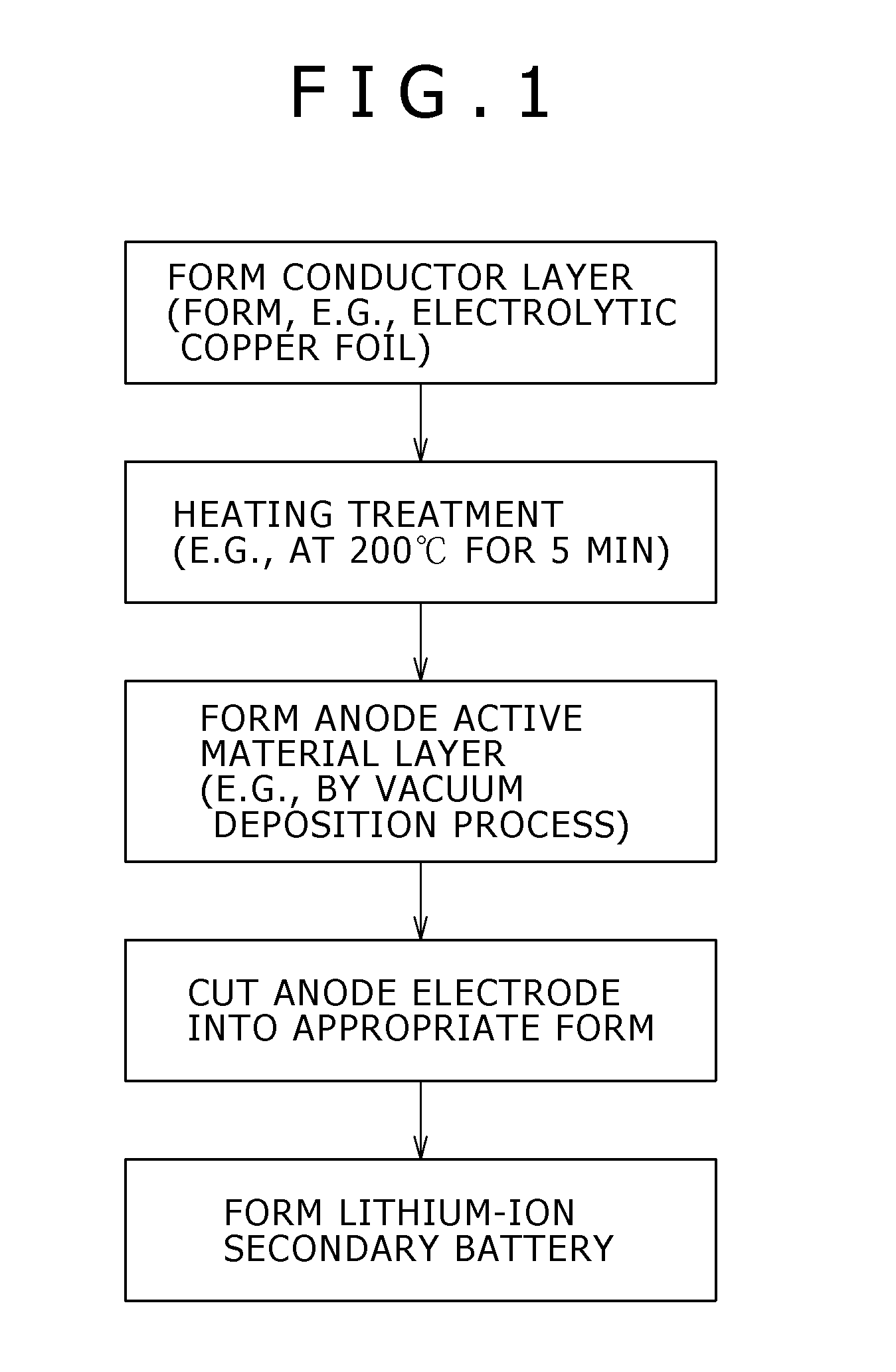
[0046]FIG. 1 is a flowchart showing the process for forming a lithium-ion secondary battery according to the present embodiment. First, a conductor layer for forming a conductive layer constituting an anode current collector, for example, an electrolytic copper foil is formed by an electrolytic process.

[0047]Then, the resultant conductor layer is subjected to heating to form a conductive layer. In this instance, the heating is preferably conducted at a temperature of 200° C. or higher for 5 minutes or longer. The heating is preferably conducted in an atmosphere of chemically inert gas, for example, in argon gas or nit...

second embodiment

[0092]In the present embodiment, an example is described in which an electrode for battery is formed using a related art electrode current collector, which is not treated by heating, and then the electrode for battery is subjected to heating, and a lithium-ion secondary battery is formed using as an anode electrode the electrode for battery treated by heating.

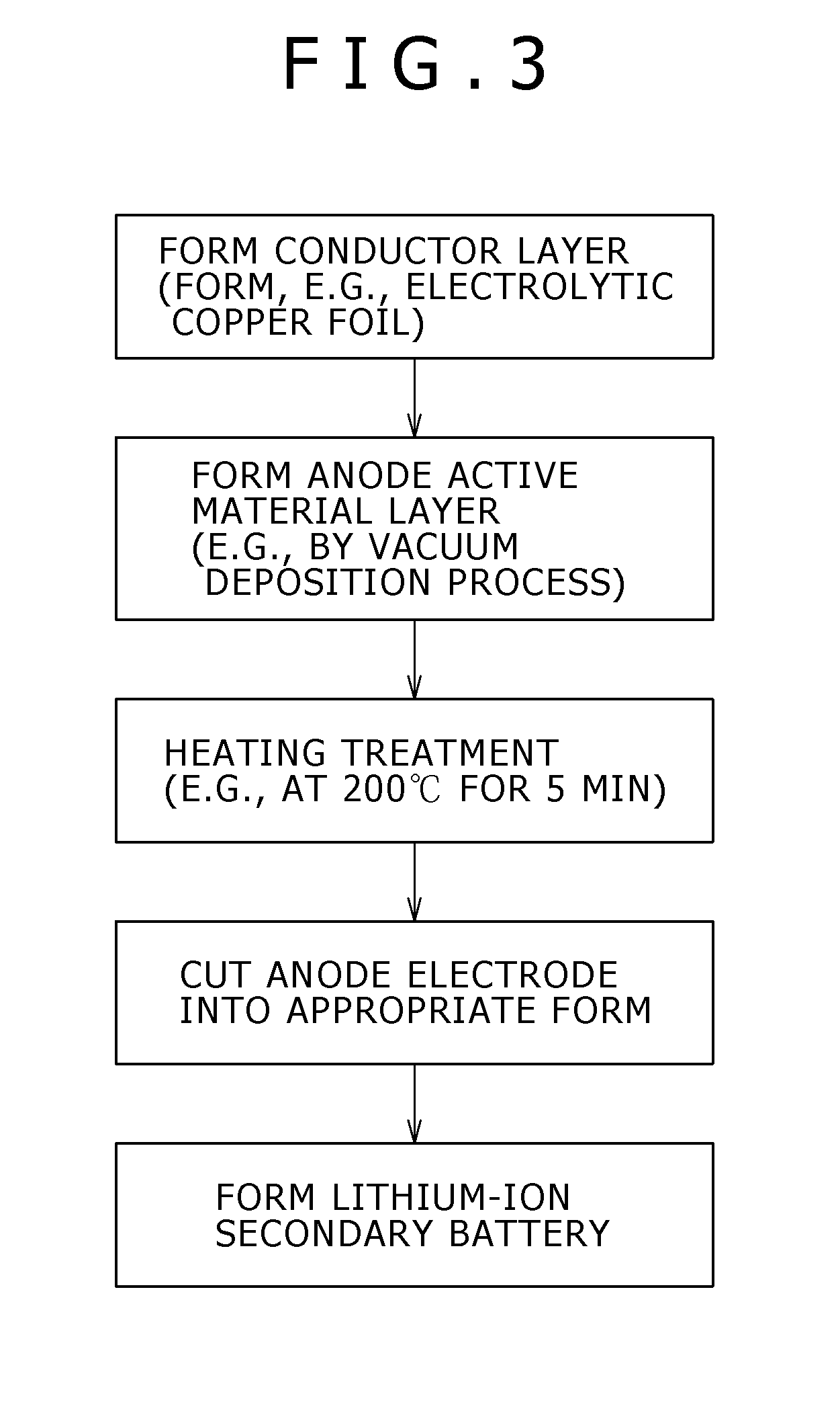
[0093]FIG. 3 is a flowchart showing the process for forming a lithium-ion secondary battery according to the present embodiment. First, a conductor layer for forming a conductive layer constituting an anode current collector, for example, an electrolytic copper foil is formed by an electrolytic process.

[0094]Next, an anode active material layer is formed on the anode current collector. The method for forming the anode active material layer is similar to that used in the first embodiment.

[0095]Then, the conductor layer of the anode current collector having formed thereon the anode active material layer is subjected to heating to...

example 1-1

[0099]In Example 1-1, an electrolytic copper foil having a surface roughened by an electrolytic treatment and having a thickness of 20 μm was used as an anode current collector material, and the anode current collector material was first subjected to heating such that the material was kept in an argon gas atmosphere of a calcination furnace at 500° C. for 10 hours. Then, a silicon layer having a thickness of 6 μm was formed on the heating-treated electrolytic copper foil by a vacuum deposition process using a deflecting electron beam evaporation source, thus forming an electrode for battery.

[0100]FIGS. 4A and 4B are photographs of the cross-section structures of electrolytic copper foils examined under a scanning electron microscope, in which the cross-sections are individually obtained by cutting by means of a microtome the electrolytic copper foil after the heating (FIG. 4A) and the electrolytic copper foil before the heating (FIG. 4B). From a comparison between FIGS. 4A and 4B, i...


PUM

PropertyMeasurementUnit
Temperatureaaaaaaaaaa
Pore sizeaaaaaaaaaa

Abstract

A current collector forming an electrode for battery is provided. The electrode current collector includes a conductive layer made of copper or a copper alloy. Furthermore, the conductive layer has a plurality of crystallites, the crystallites containing crystallites having a cross-section area of 20 μm2 or more.

Description

CROSS-REFERENCE TO RELATED APPLICATIONS[0001]The present application contains subject matter related to Japanese Patent Application JP 2006-174763 filed in the Japanese Patent Office on Jun. 26, 2006, the entire contents of which being incorporated herein by reference.BACKGROUND OF THE INVENTION[0002]1. Field of the Invention[0003]The present invention relates to an electrode current collector that may be advantageously used in, e.g., lithium secondary battery, and a method for producing the same, an electrode for battery and a method for producing the same, and a secondary battery. More particularly, the present invention relates to the improvement of discharge capacity and cycle characteristics.[0004]2. Description of Related Art[0005]In recent years, mobile devices are being improved in performance and increased in functions, and, in accordance with this tendency, demands are made on secondary batteries used as a power source of the mobile devices, in which the batteries should b...

Claims


Application Information

Patent Timeline
IPC IPC(8): H01M4/38B05D3/00H01M4/58B32B15/04H01M4/02H01M4/04H01M4/13H01M4/134H01M4/1395H01M4/66H01M4/80H01M10/05H01M10/052H01M10/0567H01M10/0569
CPCH01M4/134H01M4/1395H01M4/661Y02E60/122H01M10/052H01M10/0569H01M2004/021H01M4/667Y02E60/10Y10T428/31678Y02P70/50H01M4/0471H01M4/386H01M4/387
Inventor IWAMA, MASAYUKIIMOTO, RIKAKOKAWASE, KENICHIKITA, AKINORI
Owner MURATA MFG CO LTD
Why Eureka
Try Eureka