Techniques for Improving the Performance and Extending the Lifetime of an Ion Source with Gas Mixing

a technology of ion source and ion beam, which is applied in the field of improving the performance of the ion source, can solve the problems of unstable ion source 102 output, ion source failure, and material accumulation on the cathode surface, etc., and achieves the effects of improving performance, extending the lifetime of an ion source, and improving performan

Active Publication Date: 2008-10-02
VARIAN SEMICON EQUIP ASSOC INC
View PDF11 Cites 82 Cited by
  • Summary
  • Abstract
  • Description
  • Claims
  • Application Information

AI Technical Summary

Benefits of technology

[0017]Techniques for improving the performance and extending the lifetime of an ion source with gas mixing are disclosed. In one particular exemplary embodiment, the techniques may be realized as a method for improving performance and extending lifetime of an ion source in an ion implanter. The method may comprise releasing a predetermined amount of dopant gas into an ion source chamber. The dopant gas may comprise a dopant species. The method may also comprise releasing a predetermined amount of diluent gas into the ion source chamber. The diluent gas may dilute the dopant gas to improve the performance and extend the lifetime of the ion source.
[0024]In accordance with another exemplary embodiment, the techniques may be realized as an apparatus for improving performance and extending lifetime of an ion source in an ion implanter. The apparatus may comprise a dopant gas controller for releasing a predetermined amount of dopant gas from a dopant gas source into an ion source chamber. The dopant gas may comprise a dopant species. The apparatus may also comprise a first diluent gas controller for releasing a predetermined amount of a first diluent gas from a first diluent gas source into the ion source chamber. The first diluent gas may dilute the dopant gas to improve the performance and extend the lifetime of the ion source.
[0025]In accordance with another exemplary embodiment, the techniques may be realized an apparatus for improving performance and extending lifetime of an ion source in an ion implanter. The system may comprise an ion source have a dopant gas controller to release a predetermined amount of dopant gas from a dopant gas source into an ion source chamber. The dopant gas may comprise a dopant species. The system may also comprise one or more diluent gas controllers to release a predetermined amount of one or more diluent gases from one or more diluent gas sources into the ion source chamber. The one or more diluent gases may comprise one or more co-species. The dopant gas and the one or more diluent gases may form a complementary mixture to improve the performance and extend the lifetime of the ion source.

Problems solved by technology

A common cause of ion source failure is that some materials accumulate on cathode surfaces during extended use of the ion implanter system 100.
Furthermore, this change in the condition of the cathode 208, the repeller electrode 210, or extraction electrodes 240 may result in unstable output of ions from the source 102 which is highly undesirable.
This may result in beam current drifts and, in some cases, a higher frequency of glitches, both of which may be critical metrics towards the performance of an ion source.
As a result, performance degradation and short lifetime of the ion source 102 greatly reduces the productivity of the ion implanter system 100.
However, very short lifetimes of ion sources have been observed while operating with GeF4 dopant gas.
Although an inert gas, such as argon, xenon, etc., may be used as a dopant gas, using inert gases, even though they do not contain fluorine, inevitably result in reduced beam currents.
As a result, ion source operation, such as performance and lifetime, is still greatly reduced.
Another common cause of ion source failure is caused by stripping (or sputtering) of material from the cathode 208 during source operation.
These adverse effects are particularly noticeable when using hydrides (e.g., AsH3, PH3, CH4, etc.), inert gases (Ar, Xe, etc.), or a mixture thereof, as the source material of desired implantation species.

Method used


Image

  • Techniques for Improving the Performance and Extending the Lifetime of an Ion Source with Gas Mixing
  • Techniques for Improving the Performance and Extending the Lifetime of an Ion Source with Gas Mixing
  • Techniques for Improving the Performance and Extending the Lifetime of an Ion Source with Gas Mixing

Examples


Embodiment Construction

[0033]Embodiments of the present disclosure improve the performance and extend the lifetime of an ion source with gas mixing.

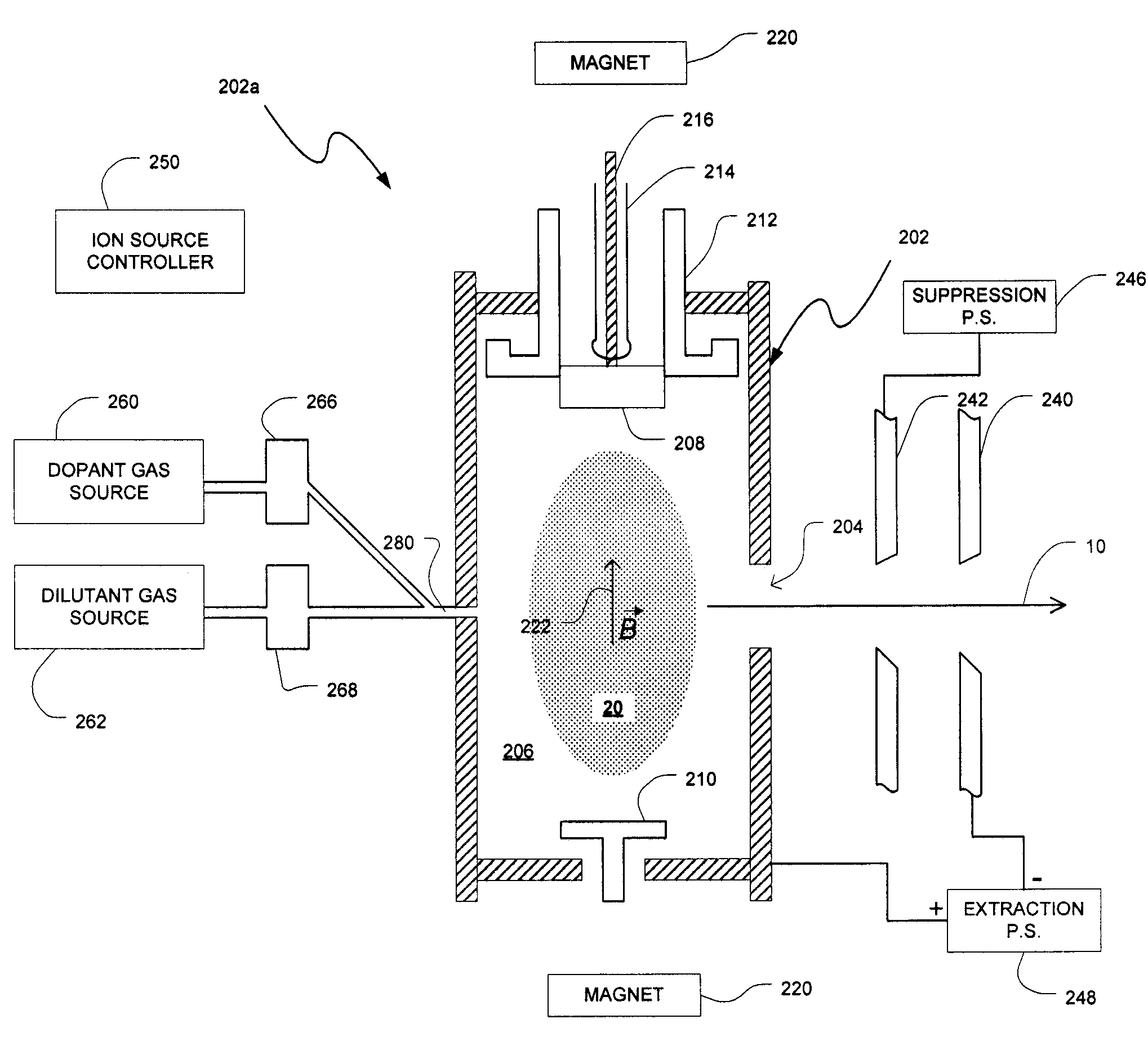
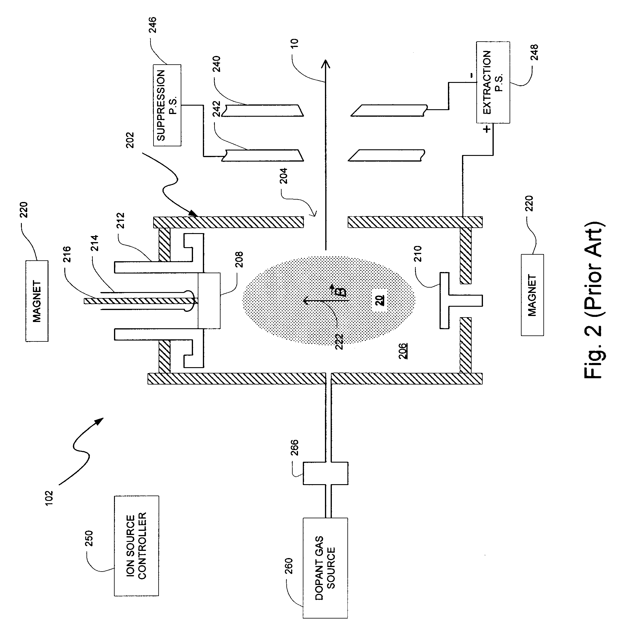
[0034]FIGS. 3A-3C depict exemplary ion source configurations 202a and 202b, respectively, in accordance with embodiments of the present disclosure. It should be appreciated by one skilled in the art that all of the elements of FIG. 2 are incorporated into FIGS. 3A-3C. As a result, most of the elements in FIGS. 3A-3C should be understood in relation to the elements in FIG. 2.

[0035]Referring to FIG. 3A, an ion source 202a may comprise one or more diluent gas sources to release one or more diluent gases into the arc chamber 206 to dilute a dopant gas from the dopant gas source 260. For example, a diluent gas source 262 and an associated gas flow controller 268 may provide a predetermined amount of diluent gas to the arc chamber 206 via a conduit 280 to dilute a dopant gas from the dopant gas source 260.

[0036]In one embodiment, as depicted in FIG. 3A, the dopant g...


PUM


Abstract

Techniques improving the performance and extending the lifetime of an ion source with gas mixing are disclosed. In one particular exemplary embodiment, the techniques may be realized as a method for improving performance and extending lifetime of an ion source in an ion implanter. The method may comprise introducing a predetermined amount of dopant gas into an ion source chamber. The dopant gas may comprise a dopant species. The method may also comprise introducing a predetermined amount of diluent gas into the ion source chamber. The diluent gas may dilute the dopant gas to improve the performance and extend the lifetime of the ion source. The diluent gas may further comprise a co-species that is the same as the dopant species.

Description

FIELD OF THE DISCLOSURE[0001]The present disclosure relates generally to semiconductor manufacturing equipment and, more particularly, to techniques for improving the performance and extending the lifetime of an ion source with gas mixing.BACKGROUND OF THE DISCLOSURE[0002]Ion implantation is a process of depositing chemical species into a substrate by direct bombardment of the substrate with energized ions. In semiconductor manufacturing, ion implanters are used primarily for doping processes that alter the type and level of conductivity of target materials. A precise doping profile in an integrated circuit (IC) substrate and its thin-film structure is often crucial for proper IC performance. To achieve a desired doping profile, one or more ion species may be implanted in different doses and at different energy levels.[0003]FIG. 1 depicts a conventional ion implanter system 100. The ion implanter system 100 may comprise an ion source 102 and a complex series of components through wh...

Claims


Application Information

Patent Timeline
Patent Type & Authority Applications(United States)
IPC IPC(8): G21K5/10
CPCH01J37/08H01J2237/022H01J37/3171H01J37/30H01L21/265
Inventor GUPTA, ATUL
Owner VARIAN SEMICON EQUIP ASSOC INC
Why Eureka
Try Eureka