
Method for producing powder forsterite powder, forsterite powder, sintered forsterite, insulating ceramic composition, and multilayer ceramic electronic component

Active Publication Date: 2008-10-16
MURATA MFG CO LTD
View PDF7 Cites 9 Cited by
  • Summary
  • Abstract
  • Description
  • Claims
  • Application Information

AI Technical Summary

Benefits of technology

[0047]If the forsterite powder has a structure in which copper is contained at crystal grain boundaries in an amount of 300 to 2,000 ppm by weight, the forsterite powder can achieve superior characteristics because MgO and SiO2 react sufficiently even at low firing temperature and substantially no unreacted magnesium-based component remains.
[0048]The forsterite powder having the above structure can be efficiently produced by the method for producing a forsterite powder of the present invention.
[0053]If the crystal size exceeds 0.040 μm, the forsterite powder has a particle size of more than 0.4 μm. Such a forsterite powder has poor sinterability. If the forsterite powder is used to produce, for example, a ceramic substrate, a large amount of glass must be added to improve the sinterability. This is undesirable because the glass causes the problem of degrading of characteristics such as the Q factor (the reciprocal of the dielectric loss δ).
[0055]As insulating ceramic composition of the present invention includes a first ceramic powder mainly including the above forsterite powder; a second ceramic powder formed of at least one material selected from the group consisting of a ceramic powder mainly containing calcium titanate, a ceramic powder mainly containing strontium titanate, and a ceramic powder mainly containing titanium oxide; and a borosilicate glass powder. The borosilicate glass contains 3% to 15% by weight of lithium on a Li2O basis, 30% to 50% by weight of magnesium on a MgO basis, 15% to 30% by weight of boron on a B2O3 basis, 10% to 35% by weight of silicon on a SiO2 basis, 6% to 20% by weight of zinc on a ZnO basis, and 0% to 15% by weight of aluminum on an Al2O3 basis. This insulating ceramic composition is suitable for production of electronic components.
[0059]A multilayer ceramic electronic component of claim 12 of the present invention includes laminated insulating ceramic layers and the wiring conductors associated with the above insulating ceramic layers. The insulating ceramic layers are formed of the insulating ceramic composition, so that the multilayer ceramic electronic component is compact, has high performance, and is economically advantageous.
[0060]The insulating ceramic layers are formed of the insulating ceramic composition prepared using the forsterite powder of the present invention. In addition, the wiring conductors are formed using a metal with low resistivity, such as copper or silver, as a major component. The insulating ceramic layers have a low relative dielectric constant, superior temperature-dependent characteristics of resonant frequency, and a high Q factor, thus providing a highly reliable multilayer ceramic electronic component suitable for high-frequency applications.

Problems solved by technology

The above technique, however, has the problem of increased equipment costs because it requires special equipment, such as an ultrasonic atomizer, for firing the liquid microparticles in a suspended state and powder separation equipment, such as a cyclone separator, for separating the resultant forsterite particles.
A common method in which a mixture of Mg(OH)2 and SiO2 is allowed to react by firing rather than using the method of firing in a suspended state, as in Patent Document 1, has the problem of increased thermal energy costs for firing because the firing temperature must be raised to around 1,200° C. Another problem is that firing under high-temperature conditions approaching 1,200° C. causes the particles of forsterite powder to grow to an excessive particle size for use as a material for electronic components.

Method used


Image

  • Method for producing powder forsterite powder, forsterite powder, sintered forsterite, insulating ceramic composition, and multilayer ceramic electronic component
  • Method for producing powder forsterite powder, forsterite powder, sintered forsterite, insulating ceramic composition, and multilayer ceramic electronic component
  • Method for producing powder forsterite powder, forsterite powder, sintered forsterite, insulating ceramic composition, and multilayer ceramic electronic component

Examples


example 1

Production of Forsterite Powder

[0098]In Example 1, forsterite powders were produced by the following procedure.

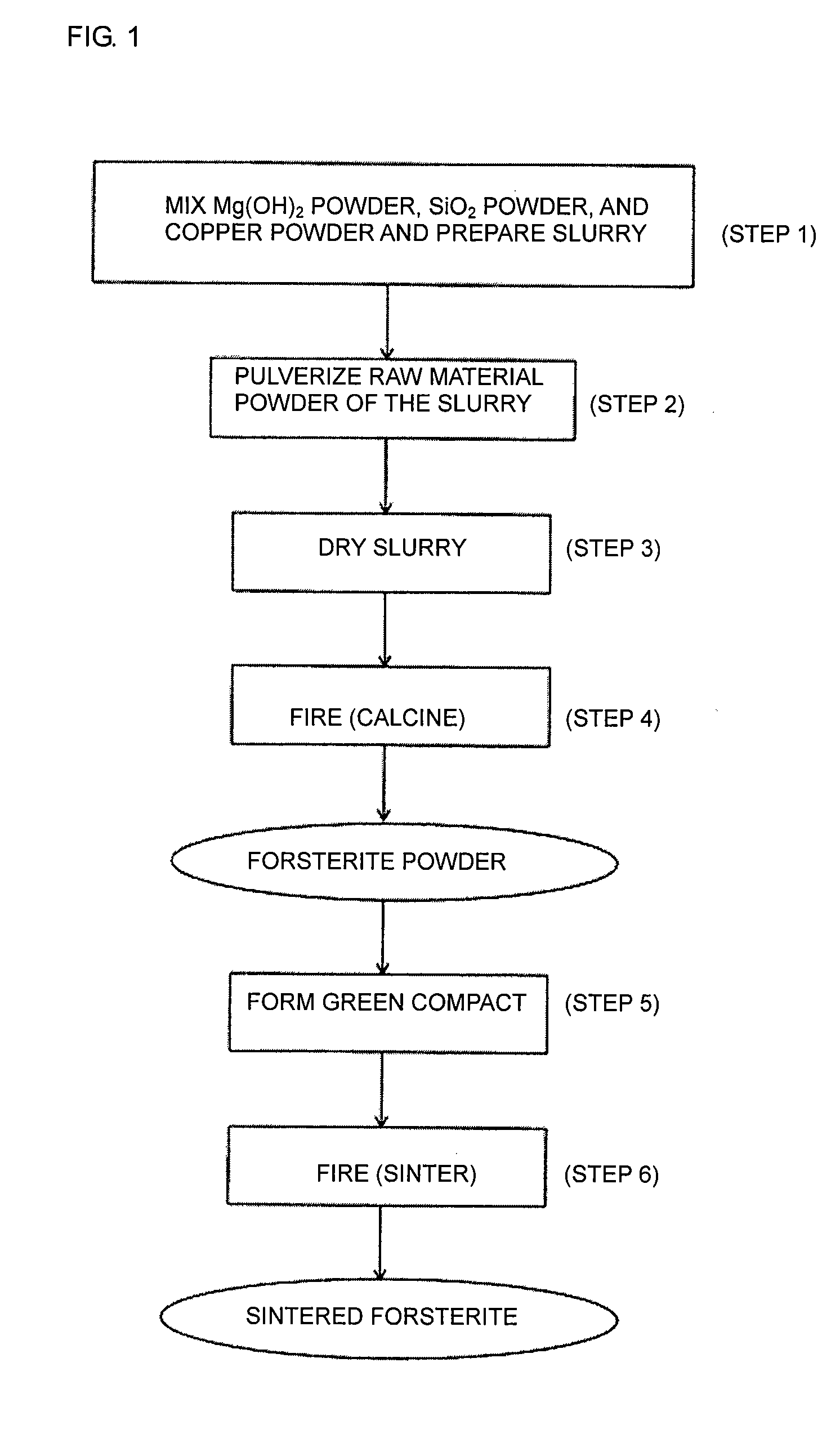
[0099]The method for producing the forsterite powders of Example 1 will now be described with reference to FIG. 1, which shows the production process.

(1) Mixing of Raw Materials and Preparation of Slurry

[0100]First, Mg(OH)2 powder and SiO2 powders were weighed out so that the molar ratio of MgO to SiO2 (Mg(OH)2 / SiO2) of the forsterite (2MgO.SiO2) powders obtained after firing (calcination) was 1.97.

[0101]In addition, a copper sol (dispersing medium: water) was weighed out so that the contents of copper in the forsterite powders obtained after firing (calcination) were the values shown in Table 1.

[0102]The Mg(OH)2 powder used in Example 1 had an average particle size of 2.5 μm, and the SiO2 powder had an average particle size of 1.5 μm.

[0103]The copper sol had an average particle size of less than 0.05 μm. These raw materials were added to a dispersing medium, namely, pure w...

example 2

[0118]FIG. 4 is a sectional view of a ceramic multilayer module 1 as an example of a multilayer ceramic electronic component produced using an insulating ceramic composition containing a forsterite powder according to the present invention. FIG. 5 is an exploded perspective view of the ceramic multilayer module 1 shown in FIG. 4.

[0119]The ceramic multilayer module 1 includes a multilayer ceramic substrate 2. The multilayer ceramic substrate 2 includes a laminate of insulating ceramic layers 3 and high-dielectric-constant ceramic layers 4. The high-dielectric-constant ceramic layers 4 are between the insulating ceramic layers 3.

[0120]The insulating ceramic layers 3 are formed of insulating sintered ceramic compacts produced by firing an insulating ceramic composition according to the present invention. The insulating ceramic layers 3 have a relatively low relative dielectric constant of, for example, 10 or less.

[0121]Specifically, the insulating ceramic composition used for the insul...

example 3

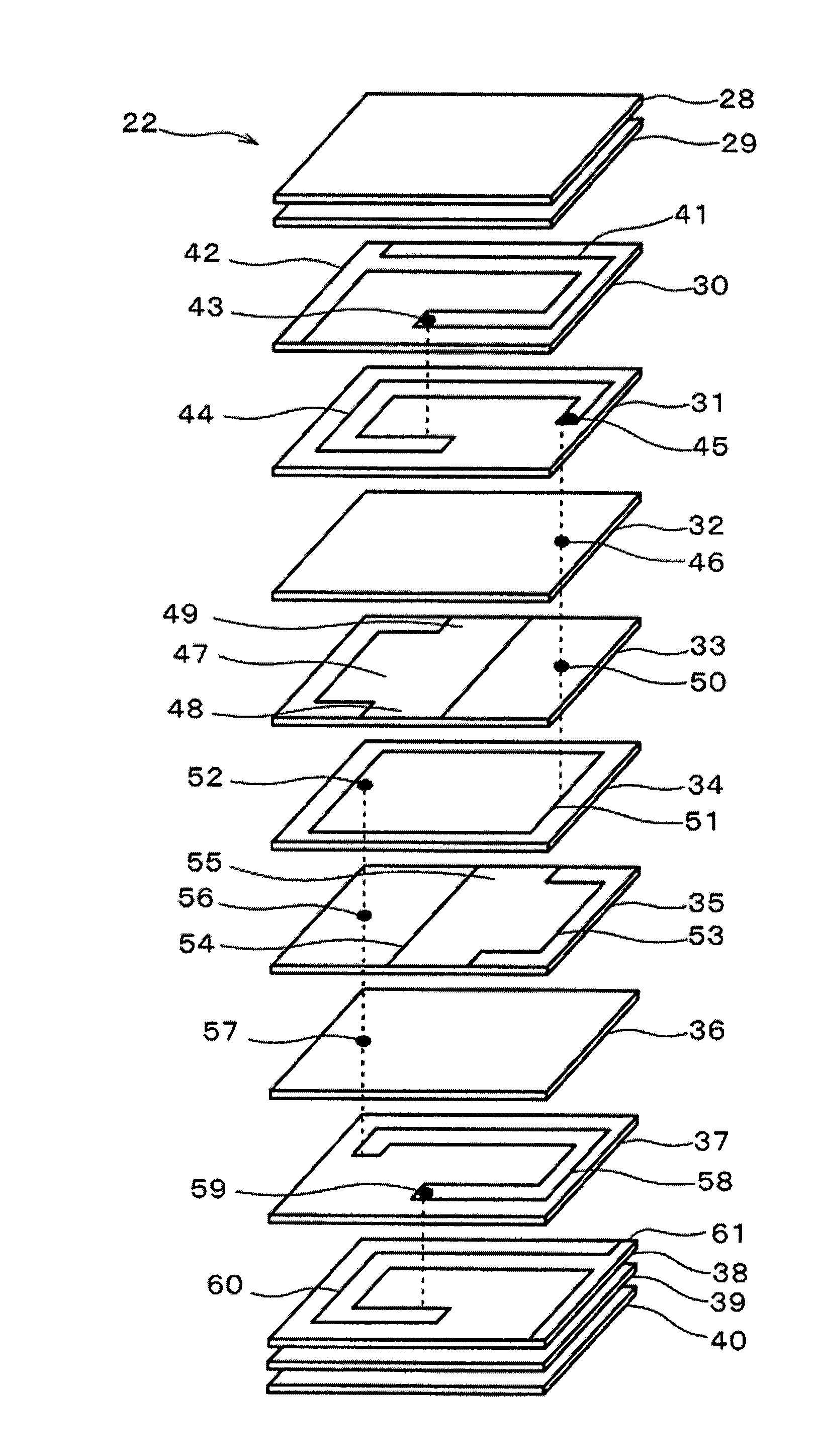
[0137]FIGS. 7 and 8 are diagrams of an LC filter 21 as another example (Example 3) of a multilayer ceramic electronic component produced using an insulating ceramic composition containing a forsterite powder according to the present invention. FIG. 7 is a perspective view showing the appearance of the LC filter 21. FIG. 8 is an equivalent circuit diagram of the LC filter 21. FIG. 9 is an exploded perspective view of an unfired laminate 22 as an intermediate product to be subjected to a firing step in the production of the LC filter.

[0138]In FIG. 7, the LC filter 21 of Example 3 includes a component body 23 having a multilayer structure of insulating ceramic layers, terminal electrodes 24 and 25 disposed on opposing ends of the component body 23, and terminal electrodes 26 and 27 disposed midway along the sides of the component body 23.

[0139]In FIG. 8, the LC filter 21 includes two inductances L1 and L2 directly connected between the terminal electrodes 24 and 25 and a capacitance C ...


PUM

PropertyMeasurementUnit
Lengthaaaaaaaaaa
Fractionaaaaaaaaaa
Fractionaaaaaaaaaa

Abstract

A forsterite powder with superior characteristics which can be sintered at a relatively low temperature can be economically produced, when a magnesium source, a silicon source, and copper particles are mixed to prepare a mixed powder containing 300 to 2,000 ppm by weight of the copper particles, and the mixed powder is fired. The magnesium source used is preferably Mg(OH)2, and the silicon source used is preferably SiO2. A polycrystalline forsterite powder is preferably produced. The magnesium source, the silicon source, and the copper particles can be mixed in the presence of a solvent to prepare the mixed powder. The forsterite powder preferably contains 300 to 2,000 ppm by weight of copper, has a particle size of 0.20 to 0.40 μm and has a crystal size of 0.034 to 0.040 μm.

Description

[0001]This is a continuation of application Ser. No. PCT / JP2006 / 323848, filed Nov. 29, 2006.TECHNICAL FIELD [0002]The present invention relates to a method for producing a forsterite powder by mixing and firing a magnesium source such as Mg(OH)2 powder, a silicon source such as SiO2 powder, and copper particles, and also relates to a forsterite powder, sintered forsterite, a forsterite-based insulating ceramic composition, and a multilayer ceramic electronic component produced using a forsterite-based ceramic material.BACKGROUND ART [0003]Forsterite, a material used for production of ceramic electronic components, is usually produced by mixing and pulverizing Mg(OH)2 powder and SiO2 powder and firing the mixture so that the Mg(OH)2 and SiO2 react with each other.[0004]One method for producing a forsterite powder has been proposed in Patent Document 1. In this method, forsterite (a magnesium-containing oxide powder) is produced by forming liquid microparticles of a solution containin...

Claims


Application Information

Patent Timeline
IPC IPC(8): C01B33/22C04B35/195H05K1/03
CPCB82Y30/00Y10T428/2982C03C10/0009C04B35/20C04B35/49C04B2235/3206C04B2235/3208C04B2235/3213C04B2235/3215C04B2235/3224C04B2235/3418C04B2235/407C04B2235/5436C04B2235/5445C04B2235/5454C04B2235/6025C04B2235/656C04B2235/6567H01G4/10H01G4/1209H01G4/30H05K1/0306H01L2924/1531H01L2924/16251H01L2924/3025H01L2224/16225H01L2924/15192H01L2924/19105C01B33/22
Inventor MORIYA, YOICHIMORI, NAOYA
Owner MURATA MFG CO LTD
Features
  • Generate Ideas
  • Intellectual Property
  • Life Sciences
  • Materials
  • Tech Scout
  • Unparalleled Data Quality
  • Higher Quality Content
  • 60% Fewer Hallucinations
Learn More