Method for controlling vertical type MOSFET in bridge circuit

a technology of metaloxidesemiconductor and bridge circuit, which is applied in the direction of electronic switching, pulse generator, pulse technique, etc., can solve the problems of high-speed switching power loss and restriction, circuit complexity and expansion, and increase the resistance of the on-state mosfet, so as to reduce the power loss of the diode, improve the reverse recovery characteristic, and suppress the effect of self-turning on

Active Publication Date: 2008-10-30
DENSO CORP
View PDF5 Cites 55 Cited by
  • Summary
  • Abstract
  • Description
  • Claims
  • Application Information

AI Technical Summary

Benefits of technology

[0014]According to the above method, it is possible to switch each vertical type MOSFET into the first off mode, in which the current flowing through the built-in diode of the vertical type MOSFET is larger than the current flowing through the external diode connected in inverse-parallel with the vertical type MOSFET. Also, it is possible to switch each vertical type MOSFET into the second off mode, in which the current flowing through the built-in diode of the vertical type MOSFET is smaller than the current flowing through the external diode connected in inverse-parallel with the vertical type MOSFET. Also, it is possible to switch each vertical type MOSFET into the on state. Therefore, it is possible to reduce diode power loss, improve a reverse recovery characteristic, and suppress self turn-on.

Problems solved by technology

A reverse recovery current due to switching of a MOSFET is one factor in power loss and restriction of high speed switching.
An on-state resistance of the MOSFET may increase, and a circuit may be complicated and enlarged.
The technique disclosed in Japanese Unexamined Patent Application Publication Number H7-194105 is applicable to a lateral type MOSFET but may be unsuitable for a vertical type MOSFET, which is frequently used for high power application.
Moreover, an additional control terminal and an additional reverse bias power supply are required, which may lead to complication and enlargement of a circuit.

Method used


Image

  • Method for controlling vertical type MOSFET in bridge circuit
  • Method for controlling vertical type MOSFET in bridge circuit
  • Method for controlling vertical type MOSFET in bridge circuit

Examples


first embodiment

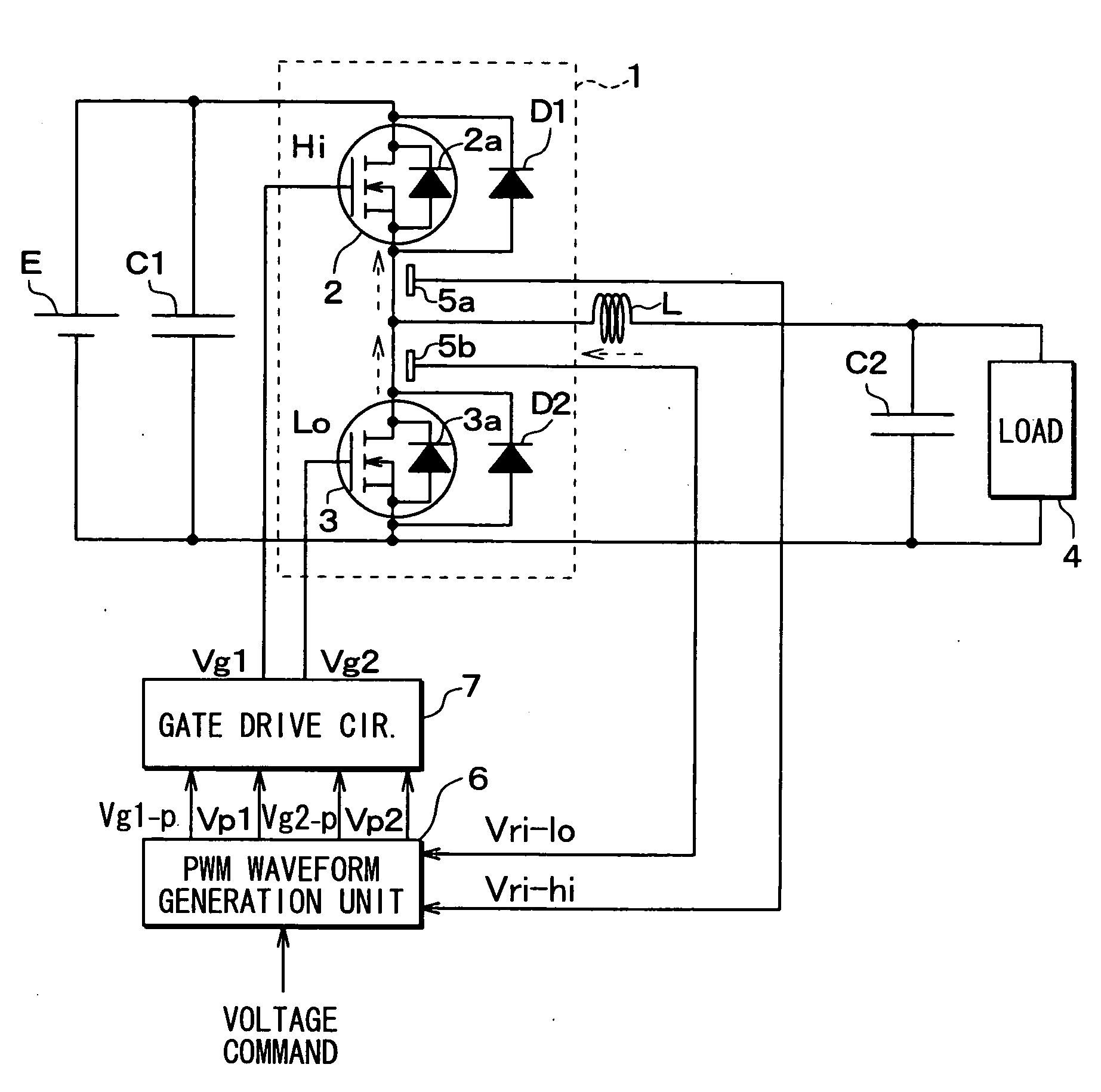
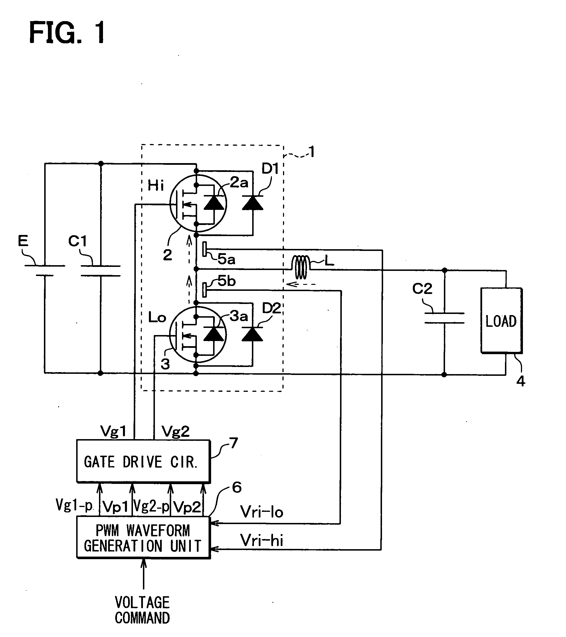
[0040]A controller of a half bridge circuit 1 and the half bridge circuit 1 including vertical type MOSFETs according to a first embodiment is described below with reference to FIGS. 1 to 6.

[0041]As shown in FIG. 1, the half bridge circuit 1 includes two vertical type MOSFETs 2, 3 connected in series and may be used as, for example, a step down inverter. In the present embodiment, an N channel accumulation-mode vertical type MOSFETs, which includes an N-channel layer disposed between a P type base layer and a gate oxidation layer, is used as each MOSFET 2, 3. Alternatively, an inversion-mode vertical type MOSFET may be used as each MOSFETs 2, 3.

[0042]An external diode D1 is connected in parallel with a built-in diode 2a of the vertical type MOSFET 2. An external diode D2 is connected in parallel with a built-in diode 3a of the vertical type MOSFET 3. A gate voltage of each MOSFET 2, 3 can control a forward voltage Vf of the built-in diode 2a, 3a of each MOSFET 2, 3. Both ends of the...

second embodiment

[0078]A controller of a half bridge circuit 1 and the half bridge circuit 1 including vertical type MOSFETs according to a second embodiment is described below. FIG. 1 is a circuit diagram also illustrating the controller of the half bridge circuit 1 and the half bridge circuit 1 according to the second embodiment. A timing to switch on the Lo-MOSFET 3 after the dead time and a timing for the reverse recovery phenomenon to occur in the Hi-MOSFET 2 are explained below with reference to a case where the current flowing through the inductor L is directed to the line between the two vertical type MOSFET 2, 3. The arrow shown in FIG. 1 corresponds to the above-described direction of the current.

[0079]FIG. 8 is a timing chart according to the present embodiment, the timing chart illustrating a representative waveform of the gate signal Vg1 for the Hi-MOSFET 2 and a representative waveform of the gate signal Vg2 for the Lo-MOSFET 3. In FIG. 8, a symbol VIIIA shows the dead time, a symbol V...

third embodiment

[0084]A controller of a half bridge circuit 1 and the half bridge circuit 1 including vertical type MOSFETs according to a third embodiment is described below. FIG. 1 is a circuit diagram also illustrating the controller of the half bridge circuit 1 and the half bridge circuit 1 according to the third embodiment.

[0085]A timing chart according to the present embodiment is shown in FIG. 9, which illustrates a representative waveform of the gate signal Vg1 of the Hi-MOSFET 2 and a representative waveform of the gate signal Vg2 of the Lo-MOSFET 3. For comparison, a timing chart illustrating waveforms of gate signals Vg1, Vg2 according to the related art is shown in FIG. 10. In FIG. 9, a symbol IXA shows a period of the Lo-MOSFET being in the off state, and a symbol IXB shows a period of the Lo-MOSFET being in the on state. In FIG. 10, a symbol XA shows a period of the Lo-MOSFET being in the off state, and a symbol XB shows a period of the Lo-MOSFET being in the on state.

[0086]As shown i...


PUM


Abstract

A method for controlling a vertical type MOSFET in a bridge circuit is provided to reduce diode power loss and improve a reverse recovery characteristic. The method includes controlling a forward voltage of a built-in diode of the vertical type MOSFET to be a first forward voltage by setting a gate voltage of the vertical MOSFET to a first gate voltage, so that the vertical type MOSFET is switched into a first off mode; and controlling the forward voltage of the built-in diode of the vertical type MOSFET to be a second forward voltage by setting the gate voltage of the vertical MOSFET to a second gate voltage, so that the vertical type MOSFET is switched into a second off mode.

Description

CROSS REFERENCE TO RELATED APPLICATION[0001]The present application is based on Japanese Patent Application No. 2007-115584 filed on Apr. 25 2007, the disclosure of which is incorporated herein by reference.BACKGROUND OF THE INVENTION[0002]1. Field of the Invention[0003]The present invention relates to a method for controlling a vertical type Metal-Oxide-Semiconductor Field-Effect-Transistor (MOSFET) in a bridge circuit.[0004]2. Description of Related Art[0005]A reverse recovery current due to switching of a MOSFET is one factor in power loss and restriction of high speed switching. According to a conventional configuration to reduce the reverse recovery current, a fast recovery diode (FRD) or a Schottky barrier diode (SBD) is connected in parallel with the MOSFET, and a reverse blocking diode for disabling a body diode is connected with the MOSFET. The above configuration may reduce the switching loss and increase a switching speed. The parallel-connected external SBD is used for s...

Claims


Application Information

Patent Timeline
Patent Type & Authority Applications(United States)
IPC IPC(8): H03K17/04
CPCH03K17/08142H03K17/0822H03K17/165H03K17/284H03K17/6871H03K17/6877H03K17/785H03K2217/0036H02M3/155H02M3/1582Y02B70/10H02M1/0051H02M1/0009
Inventor TAKASU, HISASHIINOUE, TAKESHIKIMURA, TOMONORISASAYA, TAKANARI
Owner DENSO CORP
Why Eureka
Try Eureka