Tunable millimeter-wave MEMS phase-shifter

a phase shifter and millimeter-wave technology, applied in waveguides, delay lines, electrical equipment, etc., can solve the problems of low dispersion, low loss, compact size, etc., and achieve the effect of large tuning capacity and compact siz

Inactive Publication Date: 2008-11-06
HONEYWELL INT INC
View PDF8 Cites 23 Cited by
  • Summary
  • Abstract
  • Description
  • Claims
  • Application Information

AI Technical Summary

Benefits of technology

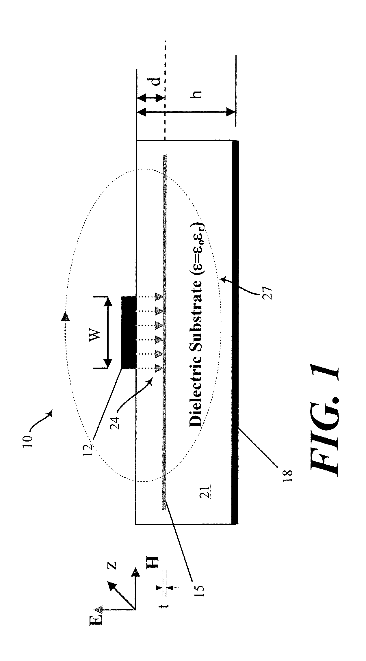
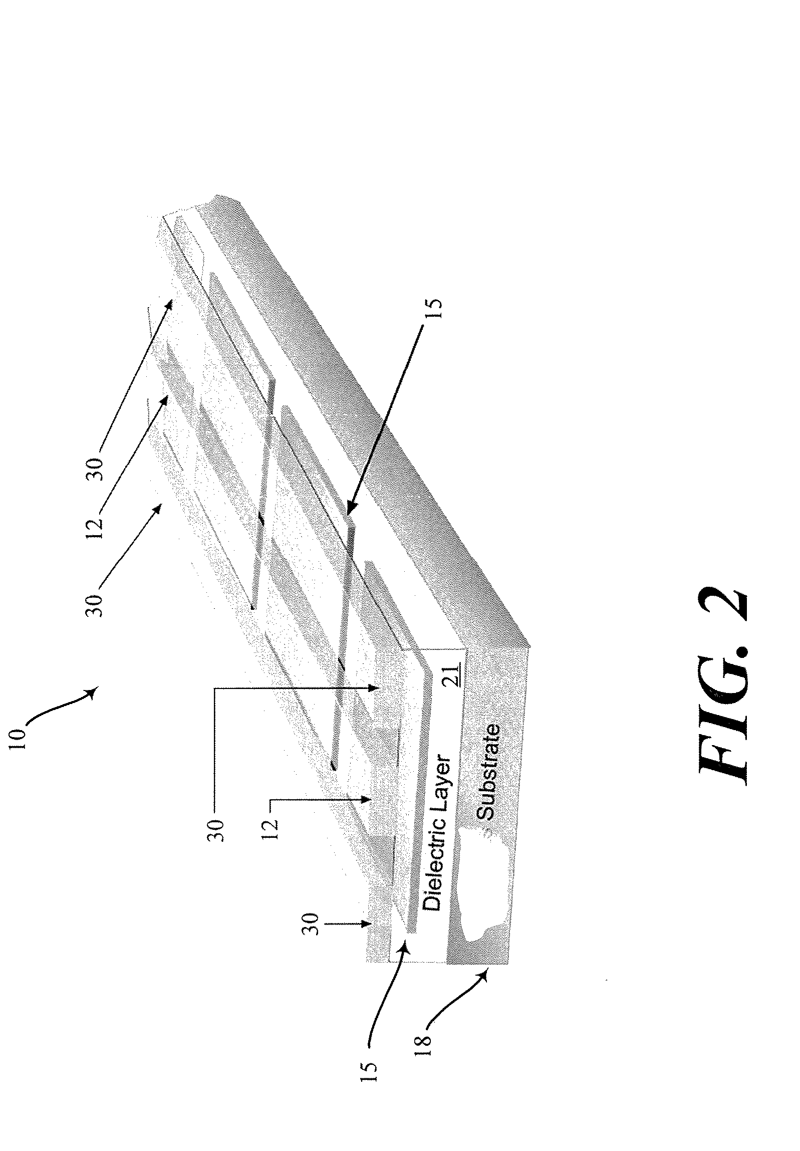
[0008]A very thin (much less than skin depth) metal screen is embedded in a dielectric layer and is configured to spatially separate the electric and magnetic fields of an electromagnetic (“EM”) wave propagates along a transmission line. A resulting spatial separation between the electric and magnetic fields results in the classic “slow-wave” mode of EM propagation thereby delaying a the EM wave with a slowing factor. Exploiting the slow wave mode of EM propagation results in low dispersion, low-loss, and compact size.
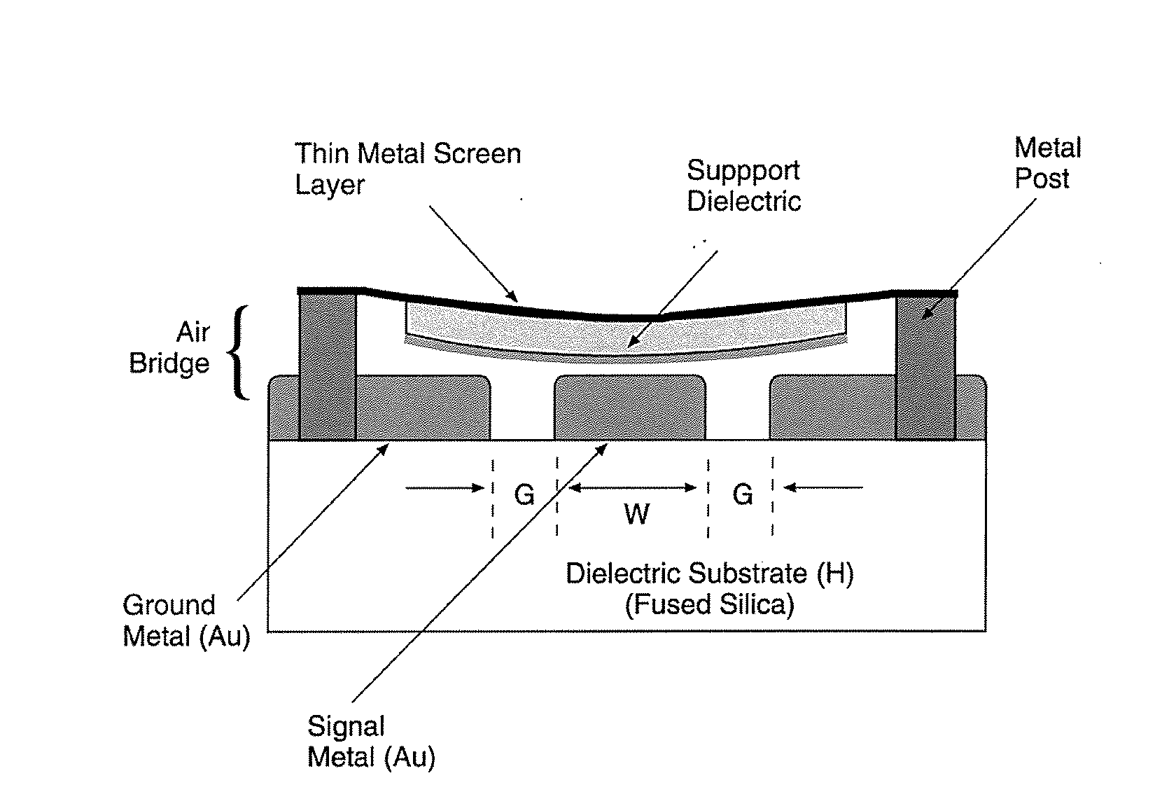
[0010]In another non-liming embodiment, a tunable phase-shifter exploits the metal screen to form an electrostatically actuated air bridge effective for tuning the phase-shifter for frequencies up to at least 100 GHz. As configured, the electrostatically actuated air bridge structure requires low actuation voltages. To further enable tuning air bridge sections are controlled individually allowing robust digital phase control.
[0011]As will be readily appreciated from the foregoing summary, the invention provides a phase-shifter that relies upon slow wave propagation having a compact size and low-dispersion, as well as a large capacity for tuning.

Problems solved by technology

Exploiting the slow wave mode of EM propagation results in low dispersion, low-loss, and compact size.

Method used


Image

  • Tunable millimeter-wave MEMS phase-shifter
  • Tunable millimeter-wave MEMS phase-shifter
  • Tunable millimeter-wave MEMS phase-shifter

Examples


Embodiment Construction

[0016]In wave theory, an antenna can be created to shape a radiated signal by energizing elements of an antenna with signals that interfere with one another. An antenna array is a plurality of antenna elements coupled to a common source or load to produce a directive radiation pattern. Usually the spatial relationship also contributes to the directivity of the antenna. For example, a phased-array is a group of antenna elements radiating signals wherein the relative phases of the respective signals feeding each of the antenna elements are offset relative to one another in such a way that the effective radiation pattern of the array is reinforced in a desired direction and suppressed in undesired directions. Phased-array technology was originally developed by the then-future Nobel Laureate Luis Alvarez during World War II to facilitate a rapidly-steerable radar system to aid pilots in the landing of airplanes in England. Other phased-radiation array technologies, such as aperture synt...


PUM


Abstract

A phase shifter for and a method for shifting phase in an antenna configured to emit a radio signal at a wavelength include a transmission line. The transmission line has a length along a primary axis and a width across a secondary axis. The primary axis and secondary axis intersect to define a waveguide plane. A conductive screen layer has first and second screen surfaces. The screen surfaces are substantially planar and disposed parallel to and spaced apart from the waveguide plane by a distance and are spaced apart from each other by a screen thickness much smaller than a skin depth of the screen layer determined at the wavelength. A dielectric layer envelopes the screen layer and has a first dielectric surface residing substantially in the waveguide plane and a second dielectric surface parallel to and spaced apart from the first dielectric surface by a height greater than the distance. A conductive ground plate has a ground plate surface substantially coplanar with the second dielectric surface whereby the propagation of the signal along the transmission line is slowed by a slowing factor.

Description

BACKGROUND OF THE INVENTION[0001]Millimeter-waves are electromagnetic (EM) waves generally between 30 and 300 GHz with wavelengths ranging from 1 to 10 mm. A millimeter wavelength is quite long compared to optical wavelengths; the long wavelength allows millimeter-waves to penetrate many optically opaque materials.[0002]Millimeter-wave ranging is of interest since most objects have high reflectivity in this range and the EM waves easily penetrate through dust, fog and smoke. A Moreover, a 94 GHz millimeter-wave radiometer may be capable of high resolution imaging with application to aviation safety and remote sensing. Millimeter-waves are non-ionizing, and effective imaging systems can be operated at extremely low power levels.[0003]Experimental millimeter wave imaging sensors using mechanically scanned antenna have proven inadequate for imaging applications due to low scanning rates mechanical scanners achieve (mechanical scanning is generally limited to frequencies of fewer than 1...

Claims


Application Information

Patent Timeline
Patent Type & Authority Applications(United States)
IPC IPC(8): H01P1/18
CPCH01P1/184H01P3/003H01P3/081
Inventor SINGH, DONALD R.
Owner HONEYWELL INT INC
Why Eureka
Try Eureka