Process and apparatus for making glass sheet

a glass sheet and glass sheet technology, applied in glass making apparatus, glass deposition burners, manufacturing tools, etc., can solve the problems of less than pristine surface quality, unwanted contamination of interface, and high cost, and achieve uniform thickness and composition, high surface quality, and high thickness uniformity

Active Publication Date: 2008-11-13
CORNING INC +1
View PDF8 Cites 51 Cited by
  • Summary
  • Abstract
  • Description
  • Claims
  • Application Information

AI Technical Summary

Benefits of technology

[0074]Certain embodiments of the process and apparatus of the present invention have one or more of the following advantages: (i) capability of forming glass sheet continuously without the need of a liquid metal bath; (ii) ability to produce glass sheet with high surface quality with minimal or no additional surface polishing; (iii) ability to

Problems solved by technology

However, this process requires direct contact between the metal melt and the glass melt, which can lead to unwanted contamination of the interface and less than pristine surface quality.
Thus, in order to produce high quality glass sheet with pristine surface properties on both major surfaces, glass sheet produced from the float process may need to be further surface-polished, which can be a quite expensive step.
Moreover, it is believed that the float process has not been used for making thin, rollable glass ribbons.
Therefore, this process cannot be used efficiently and effectively for many glass compositions.
Moreover, it is known that this process requires the use of expensive machinery.
Even though the LCD glass substrates made by fusi

Method used


Image

  • Process and apparatus for making glass sheet
  • Process and apparatus for making glass sheet
  • Process and apparatus for making glass sheet

Examples


example 1

Fabrication of a Single-Layer Soot Sheet

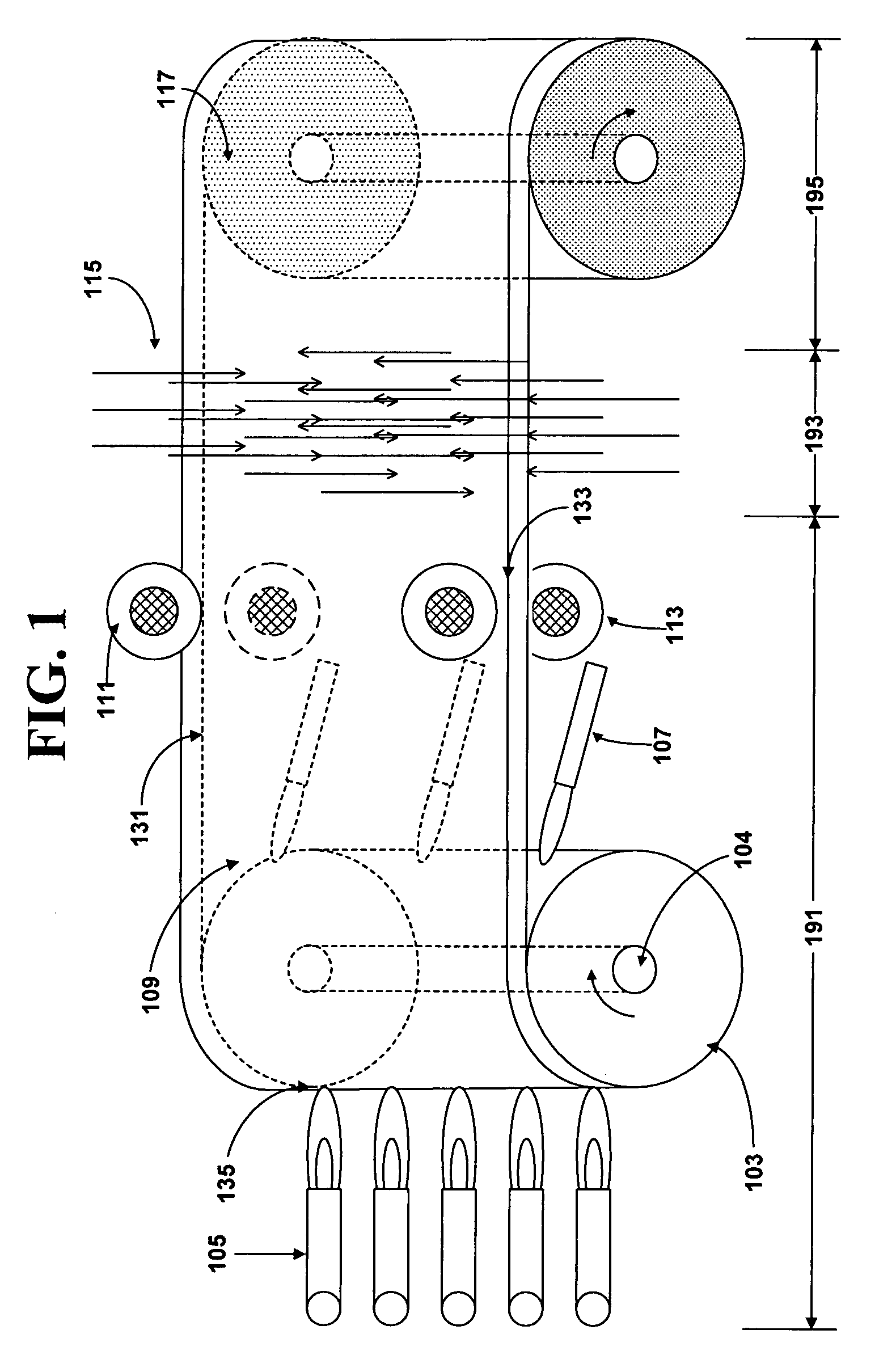
[0150]A layer of at least 99% by weight silica was produced in an apparatus according to the present invention. Five linear burners, each 1 inch wide, were mounted on a burner manifold. These burners were placed in a line, next to each other, to produce a uniform, 5 inch wide soot stream. The gasses flowed through the burners included: approximately 5 grams / minute OMCTS carried by 20 SLPM of N2 carrier gas in the centerline orifices of the burners. These gasses were surrounded along their length on both sides by a row of O2 orifices that provided approximately 5 SLPM of O2. Outside of these gasses were 2 more rows of orifices providing an additional 20 SLPM of O2. The final row of orifices, outside of the two, provided a flame to ignite the OMCTS. The flow rates were 12 SLPM of CH4 and 10 SLPM of O2.

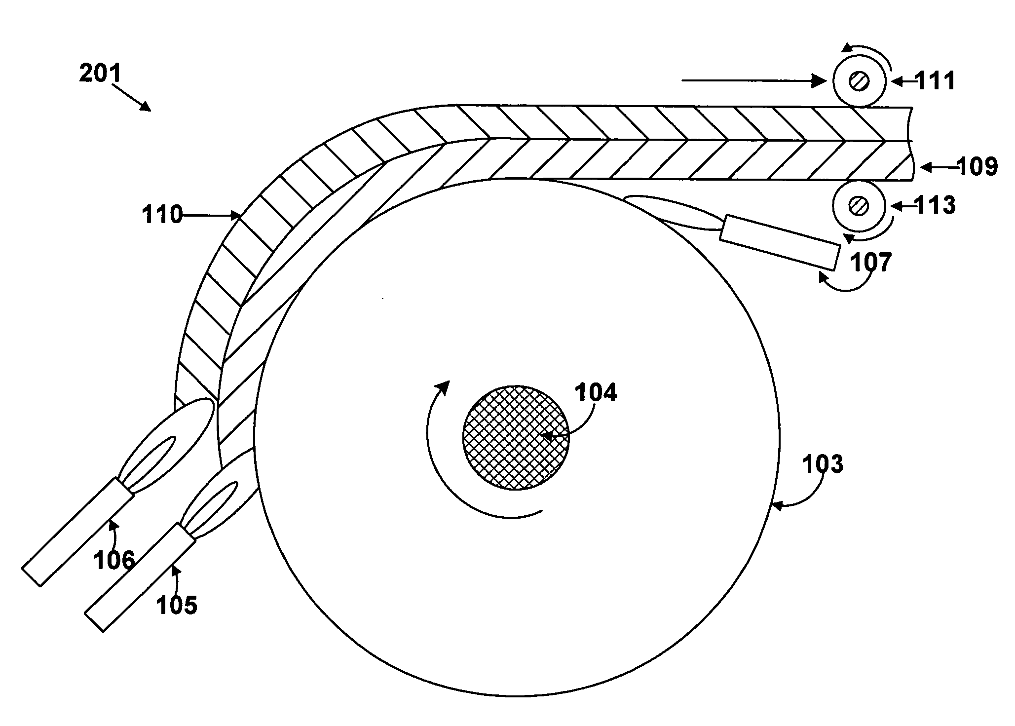
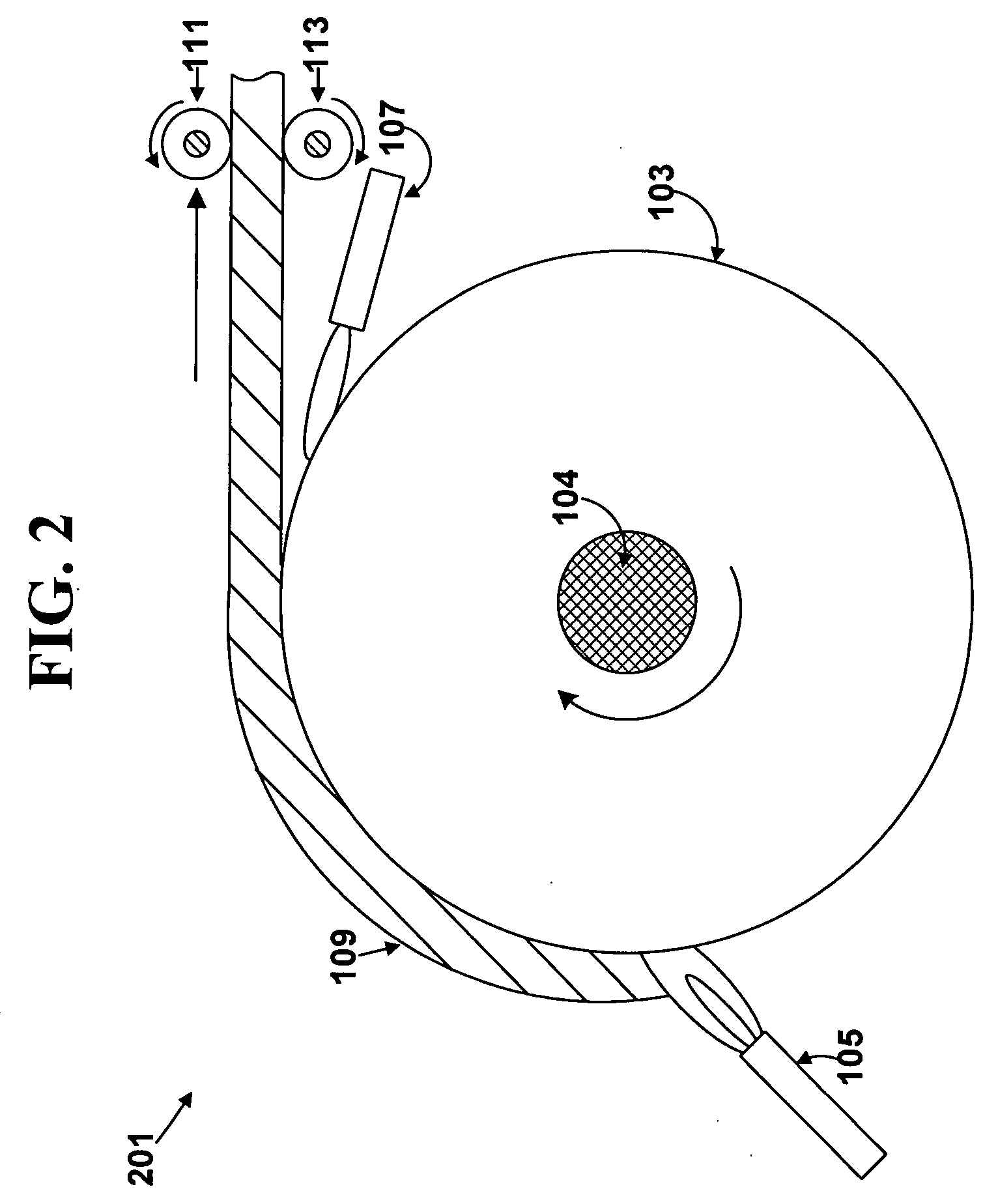
[0151]The burners were positioned approximately 4 inches from the deposition target. The target was a cylindrical quartz drum of 15 inches diamete...

example 2

Sintering of a Single-Layer Soot Sheet

[0152]A soot sheet, as described above in Example 1 but with a thickness of 60 microns was fabricated. Three of the above described burners were used in the burner array. The thickness was decreased by increasing the rotation speed of the drum and lowering the OMCTS flow rates. Thickness, density, and production rate of the soot sheet were changed by adjusting burner flow rates, drum rotation speed and distance from the burners to the drum.

[0153]A sample length, approximately 2 feet long and 3 inches wide, was taken for a sintering experiment. The peripheral edges of the soot sheet were pinned between rollers in contact along the length of the sample. A heat source was provided to sinter the soot sheet. The temperature of the soot reached approximately 1500° C. and the soot sheet densified to clear, sintered glass. The sintered glass was approximately 30 microns thick.

[0154]The sintered sheet with un-sintered peripheral edges was removed from th...


PUM

PropertyMeasurementUnit
Thicknessaaaaaaaaaa
Thicknessaaaaaaaaaa
Percent by massaaaaaaaaaa

Abstract

An apparatus and process for making glass soot sheet and sintered glass sheet. Glass soot particles are deposited on a curved deposition surface of a rotating drum to form a soot sheet. The soot sheet is then released from the deposition surface. The soot sheet can be sintered into a consolidated glass. The soot sheet and the sintered glass can be sufficiently long and flexible to be reeled into a roll.

Description

FIELD OF THE INVENTION[0001]The present invention relates to processes and apparatus for making glass sheets. In particular, the present invention relates to a soot process for making glass soot sheet and sintered glass sheet, and apparatus for such process. The present invention is useful, for example, in making long, flexible, rollable glass sheets, such as silica glass sheets.BACKGROUND OF THE INVENTION[0002]Various commercial processes are available in the prior art for making glass sheet materials. Float process, as an example, involves the formation of glass sheet on a molten metal bath. This process can be used for making glass sheet material with a wide range of compositions. Another advantage of this process is the capability of achieving high surface quality on the side exposed to air. However, this process requires direct contact between the metal melt and the glass melt, which can lead to unwanted contamination of the interface and less than pristine surface quality. Thu...

Claims


Application Information

Patent Timeline
IPC IPC(8): C23C4/04
CPCC03B19/1453C03B19/1492C03B2207/52C03B2201/06C03B2201/02C03B19/14
Inventor HAWTOF, DANIEL WARRENBRADY, MICHAEL DONOVAN
Owner CORNING INC
Why Eureka
Try Eureka