Vacuum evaporation method

a vacuum evaporation and vacuum technology, applied in vacuum evaporation coatings, chemical vapor deposition coatings, coatings, etc., can solve the problems of reducing affecting the and affecting the quality of substrates and phosphors. , to achieve the effect of improving the utilization efficiency of film-forming materials and improving efficiency

Inactive Publication Date: 2008-11-20
FUJIFILM CORP
View PDF5 Cites 42 Cited by
  • Summary
  • Abstract
  • Description
  • Claims
  • Application Information

AI Technical Summary

Benefits of technology

[0017]The present invention has been made to solve the above-mentioned conventional problems and an object of the present invention is to provide a vacuum evaporation method used in manufacturing a radiation image conversion panel having a phosphor layer formed on a substrate by vacuum evaporation with an alkali halide-based phosphor, this method being capable of using a film-forming material making up the phosphor layer with higher efficiency owing to a heating element while also preventing the substrate and the phosphor layer formed from being adversely affected by heat from the heating element.
[0022]According to the present invention having the features as described above, a heating element for improving the utilization efficiency of a film-forming material used is provided between an evaporation source and a substrate when forming an alkali halide-based phosphor layer on the substrate by vacuum evaporation, and the temperature of the heating element (heat generation temperature) can be set at a lower, temperature than usual to prevent the temperature of the substrate and that of the phosphor formed thereon from increasing due to heat from the heating element, thus keeping the substrate and the phosphor layer from altering due to the temperature increase.
[0023]In addition, by setting the temperature of the heating element at a temperature which is lower than usual and falls within a range suitable for the alkali halide-based phosphor used, vapors which do not travel toward the substrate but is likely to diffuse can be more advantageously reflected by the heating element without unnecessary diffusion of the vapor stream (evaporation steam) of the film-forming material, whereby the film-forming material can be used with further improved efficiency.

Problems solved by technology

However, when applied to the formation of a phosphor layer for a conversion panel, the method as that described in JP 08-53763 A in which film deposition is carried out as heat is generated from the heating elements at a high temperature may cause the radiation heat from the heating elements to increase the temperature of the substrate and also that of the phosphor being formed, leading to quality deterioration of the substrate and the phosphor.
As a result, conversion panels having desired characteristics may often not be obtained.
Considering an increase in the substrate temperature, organic materials such as resins cannot be used for the substrate.
The film-forming material, when reaching the heating elements that generates heat at a temperature above its melting point, is re-evaporated to cause a vapor stream (evaporation stream) of the film-forming material to diffuse, which may result in cases where the effect of improving the utilization efficiency of the film-forming material is not fully achieved.
On the other hand, the method disclosed in JP 2007-70646 A can prevent the phosphor from changing its nature due to its temperature increase to manufacture a conversion panel having desired characteristics, but this method is not sufficient to use the film-forming material with high efficiency.

Method used


Image

  • Vacuum evaporation method
  • Vacuum evaporation method
  • Vacuum evaporation method

Examples


example 1

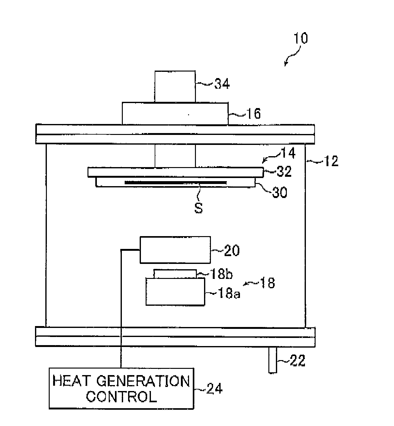
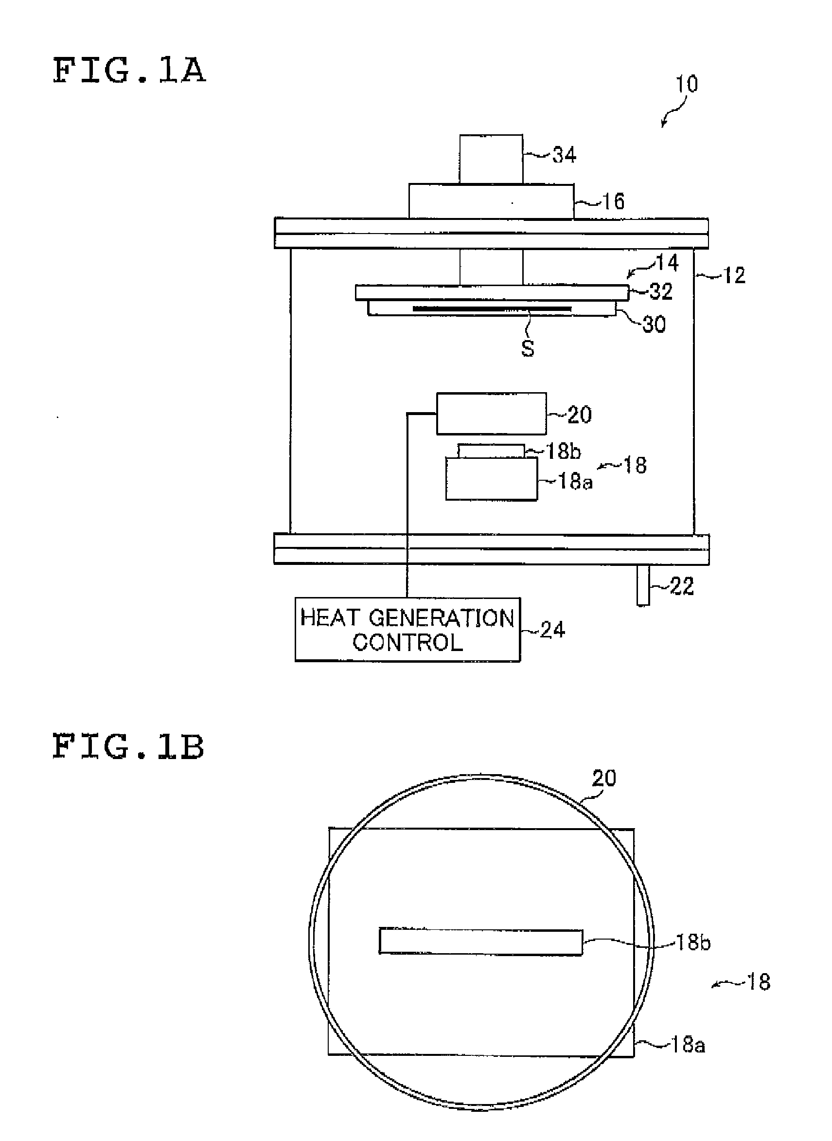
[0143]The evaporation apparatus 10 shown in FIGS. 1A and 1B was used to form a phosphor layer on the substrate S.

[0144]A tantalum crucible for resistance heating was used for the crucible 18 and a type R (platinum-rhodium) thermocouple was inserted into and fixed to the crucible 18. The upper surface of the chimney 18b (i.e., vapor outlet) was in the shape of a rectangle with a size of 8 mm×60 mm.

[0145]The crucible 18 (more specifically the crucible body 18a) was charged with 600 g of powder of cesium bromide (CsBr having a melting point of 636° C.).

[0146]A cylinder made of tungsten which has an outer diameter of 80 mm, a height of 60 mm and a plate thickness of 0.2 mm and whose upper and lower surfaces are open was fixed as the heating element 20 at a position of 0 mm just above the crucible 18 (upper end of the chimney 18b), in other words, at a position at which the upper end of the chimney 18b was flush with the lower end of the heating element 20). As shown in FIG. 1B, the heat...

examples 2 and 3

[0159]Example 1 was repeated except that an electric current of 250 A was applied to the heating element 20 to heat it to a temperature of 443.5° C. (in Example 2) and that an electric current of 380 A was applied to the heating element 20 to heat it to a temperature of 568° C. (in Example 3), thereby forming a phosphor layer (cesium bromide layer) on the substrate S. Then, the material utilization efficiency was calculated.

[0160]As a result, a material utilization efficiency of 57.2% was obtained for each case.


PUM

PropertyMeasurementUnit
temperatureaaaaaaaaaa
photosensitiveaaaaaaaaaa
luminescenceaaaaaaaaaa

Abstract

The vacuum evaporation method provides a heating element between an evaporation source of a film-forming material and a substrate; and forms a phosphor layer of an alkali halide-based phosphor on a surface of said substrate by vacuum evaporation while causing the heating element to generate heat at a temperature t (° C.) satisfying Formula (1):T−200≦t<T   (1)where T is a boiling point (° C.) of the film-forming material. This method is capable of using the film-forming material making up the phosphor layer with higher efficiency owing to a heating element while preventing the substrate and the phosphor layer from being adversely affected by heat from the heating element.

Description

BACKGROUND OF THE INVENTION[0001]The present invention relates to a vacuum evaporation method capable of improving the efficiency in using film-forming materials when manufacturing radiation image conversion panels or the like having a phosphor layer formed by means of vacuum evaporation.[0002]Nowadays, phosphors that respond in various ways to exposure to radiation (e.g. X-rays, α-rays, β-rays, γ-rays, electron beams, and ultraviolet rays) are known and find use in medical and various other fields.[0003]Upon exposure to radiation, certain types of phosphors known in the art accumulate part of the energy of the applied radiation and, in response to subsequent application of exciting light such as visible light, they emit photostimulated luminescence in an amount that is associated with the accumulated energy. These phosphors are called “stimulable phosphors” or “storage phosphors”.[0004]A radiation image information recording and reproducing system is known that employs a radiation ...

Claims


Application Information

Patent Timeline
Patent Type & Authority Applications(United States)
IPC IPC(8): C23C16/00
CPCC23C14/0694C23C14/24
Inventor NOGUCHI, YUKIHISAKASHIWAYA, MAKOTO
Owner FUJIFILM CORP
Why Eureka
Try Eureka