Active Light Sensor

a technology of active light and sensor, applied in the field of active light sensor, can solve the problems of poor spatial resolution of satellite imagery, adverse effects of cloud cover on visibility, similar problems plague aerial photographic methods, etc., and achieve the effect of improving light source performance and life, and improving performance and cos

Inactive Publication Date: 2008-11-27
KYLE H HOLLAND TRUSTEE OF THE MARANATHA TRUST DATED JULY 30 2013
View PDF26 Cites 51 Cited by
  • Summary
  • Abstract
  • Description
  • Claims
  • Application Information

AI Technical Summary

Benefits of technology

[0012]The new sensor of the present invention overcomes the time-of-day and fair weather limitations of passive technologies by incorporating its own radiant source and by rejecting the influence of ambient light on the measured canopy reflectance. Unlike passive sensor technology, this sensor will be able to operate under completely dark or full sun conditions. Additionally, the new sensor apparatus is an improvement both in performance and cost over competing active-sensor technologies commercially available. Furthermore it improves on prior art by allowing sensors to be developed that have wavelength selectivity, improved light source performance and life, and detection means and signal processing.
[0013]As discussed above, the invention presented here will be advantageous in a number of commercial applications. For site-specific agricultural applications, the developed sensor would allow the producer to reduce the amount of nitrogen fertilizer applied to a crop or facilitate spoon-feeding the crop during the growing season, thus having the potential for lowering production costs and enhancing environmental quality. Also, by being able to determine the appropriate fertilizer needs of the crop at any given location in the field, the producer can apply only the fertilizer needed to prevent yield loss or degradation of product quality (i.e., protein content in wheat and barley or sugar content in sugar beets). Subsequently, decreased fertilizer rates will substantially lower nitrogen runoff and leaching losses, which will improve the health of our watersheds, waterways, lakes, and oceans. In addition, data produced by the sensor may be used to produce relative yield maps for forecasting crop production. As for turf grass applications, the sensor technology would allow turf managers to map changes occurring on turf landscapes or for monitoring the status of turf quality.
[0014]When incorporated into variable rate applicator and / or sprayers systems, the present invention significantly reduces the use of fertilizers by precisely applying agricultural products to individual plants to be treated or eliminated. Moreover, the present invention is operable under a wide variety of conditions including cloudy conditions, bright sunlight, artificial illumination, or even total darkness. The advantage to the producer is that field operations do not have to be timed to daytime sunlight hours for operation.

Problems solved by technology

For example, early research by Resource21™ determined that during the optimal fly over times between 10 a.m. and 11 a.m. for satellite imaging, cloud cover had adverse affects on visibility.
Also, spatial resolution for satellite imagery is poor (Landsat, 20 meter and panchromatic, 10 meter).
Similar problems plague aerial photographic methods as well.
Both techniques, however, suffer from the need for extensive data processing (performed by third party providers at high cost and long lead time) and geo-referencing issues.
Even with spectroradiometric methods using sunlight as the ambient light source, cloud cover and time of day (8 a.m. to 8 p.m.) demands limit the mainstream acceptance of the technology for addressing the nitrogen rate over-loading problem.
Reusch teaches away from the use LED technology because of poor spectral selectivity and poor output radiance.

Method used


Image

  • Active Light Sensor
  • Active Light Sensor
  • Active Light Sensor

Examples


Embodiment Construction

[0028]The following contains a description for a sensor that remotely measures plant canopy chlorophyll content independent of soil reflectance and ambient illumination levels. The sensor can be used in stand-alone instrumentation configurations or in a network of sensors mounted to a vehicle or moving apparatus for on-the-go remote sensing applications. The following description of the invention is meant to be illustrative and not limiting. Other embodiments will be obvious in view of this invention.

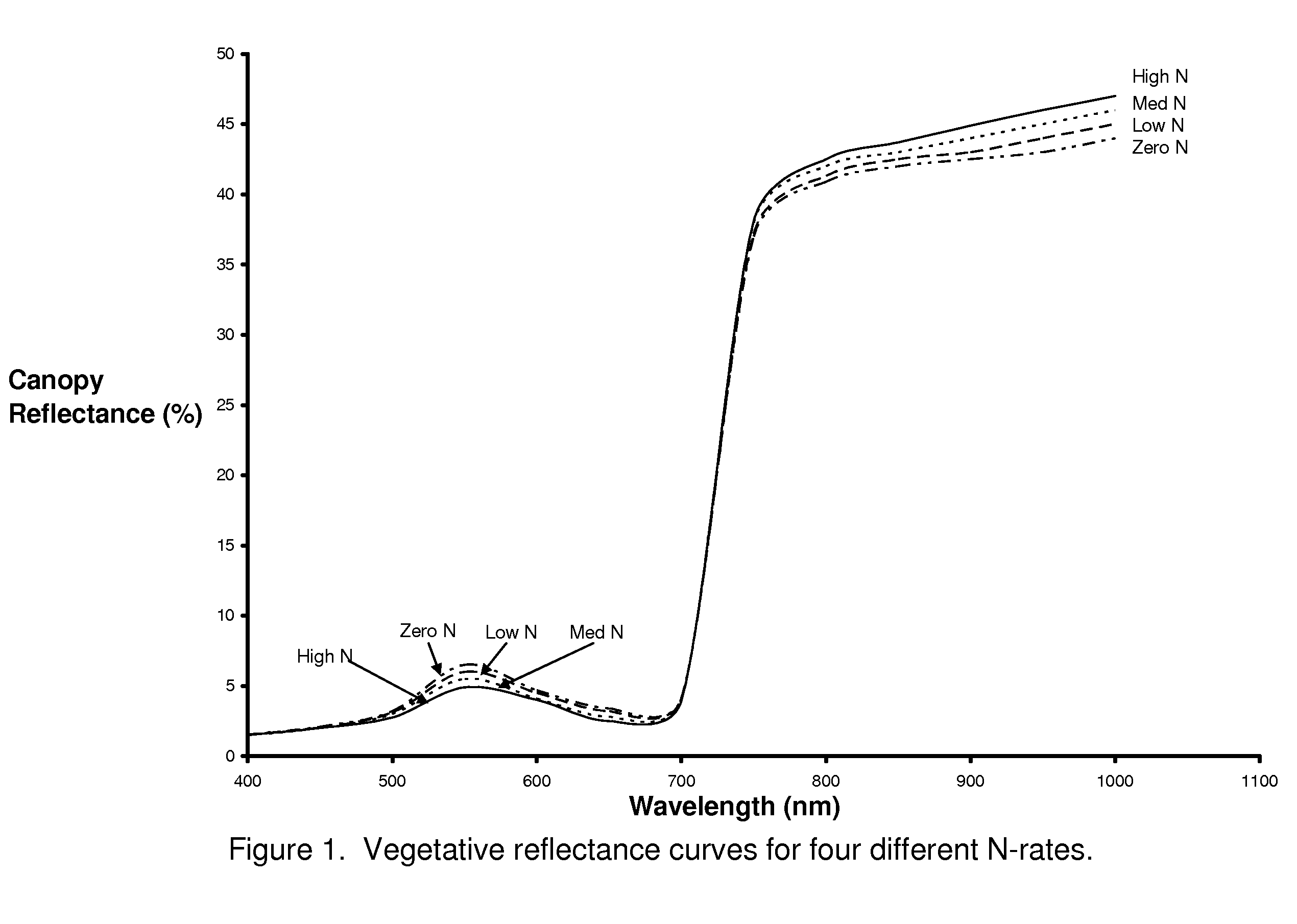
[0029]The positive relationship between leaf greenness and crop nitrogen (N) status means it should be possible to determine crop N requirements based on reflectance data collected from the crop canopy (Walberg et al., 1982; Girardin et al., 1985; Hinzman et al., 1986; Dwyer et al., 1991) and leaves (McMurtrey et al., 1994), see FIG. 1. Plants with increased levels of N typically have more chlorophyll (Inada, 1965; Rodolfo and Peregrina, 1962; Al-Abbas et al., 1974; Wolfe et al., 1988) ...


PUM

PropertyMeasurementUnit
center wavelengthsaaaaaaaaaa

Abstract

An apparatus is described for assessing plant status remotely sensed by the invention thereby allowing selective monitoring or treatment of individual plants. Additionally, the apparatus may be utilized for measuring the reflectance characteristics of soil or of objects in general. The apparatus utilizes a solid state light source to illuminate a plant canopy or object under investigation. An array of spectrally sensitive photosensors are incorporated into the apparatus to detect light reflected from a plant or object resulting from the integral light source. The instrument may be mounted to a vehicle, mounted to a tripod or held in the hand of an operator for use. A controller can be used in conjunction with the invention to analyze measured reflectance signals and can respond by activating a device to take some action with respect to the plant and / or object or store the analyzed signals with corresponding DGPS position in the controller's memory for later analysis.

Description

[0001]This invention is a continuation in part to U.S. patent application Ser. No. 10 / 703,256. This application claims priority to U.S. Provisional Application No. 60 / 925,831.BACKGROUND OF THE INVENTION[0002]1. Field of the Invention[0003]This invention relates to a structure and a method for determining changes in the chlorophyll status of a plant via remote sensing of the plant's reflectance spectrum spanning from approximately 400 nm to 900 nm.[0004]2. Description of Related Art[0005]Techniques to remotely measure crop status have historically include the use of a spectroradiometer and other instruments (Bausch et al. 1994; Chappelle et al. 1992; Maas and Dunlap, 1989), aerial photography (Benton et al, 1976), and satellite imagery.[0006]The techniques listed above are not without their limitations. For example, early research by Resource21™ determined that during the optimal fly over times between 10 a.m. and 11 a.m. for satellite imaging, cloud cover had adverse affects on visi...

Claims


Application Information

Patent Timeline
Patent Type & Authority Applications(United States)
IPC IPC(8): G01N21/55
CPCG01J3/10G01J3/36G01N21/31G01N21/3563G01N2021/3155G01N2021/635G01N2021/8466G01N2201/1244
Inventor HOLLAND, KYLE HAROLD
Owner KYLE H HOLLAND TRUSTEE OF THE MARANATHA TRUST DATED JULY 30 2013
Why Eureka
Try Eureka