Anisotropic thermal and electrical applications of composites of ceramics and carbon nanotubes

Inactive Publication Date: 2008-12-25
RGT UNIV OF CALIFORNIA
View PDF35 Cites 17 Cited by
  • Summary
  • Abstract
  • Description
  • Claims
  • Application Information

AI Technical Summary

Benefits of technology

[0011]This invention thus resides in microelectronics devices, semiconductor packages, printed circuit boards, and other devices that contain small electronic components that cause highly localized heat generation during use or that require a large difference in electrical conductivity between transverse directions, and in blades and other components of gas turbine engines, high-temperature reactors, and any vessel walls or structural components that are exposed to high-temperature environments, such devices or components having a coating, layer, or section that is formed of a uniaxially compressed composite of carbon nanotubes in a ceramic matrix. The composite can thus be a layer interposed between an exothermic device and a heat sink, or it may serve

Problems solved by technology

These include electronic devices where static is sought to be eliminated by dissipating electric charges in a plane without transmitting them across the plane, ultra-high density circuit interconnections in which the close proximity of the leads raises a risk of short circuits, solder-free connections, thermoelectric applications wh

Method used


Image

  • Anisotropic thermal and electrical applications of composites of ceramics and carbon nanotubes
  • Anisotropic thermal and electrical applications of composites of ceramics and carbon nanotubes
  • Anisotropic thermal and electrical applications of composites of ceramics and carbon nanotubes

Examples


example 1

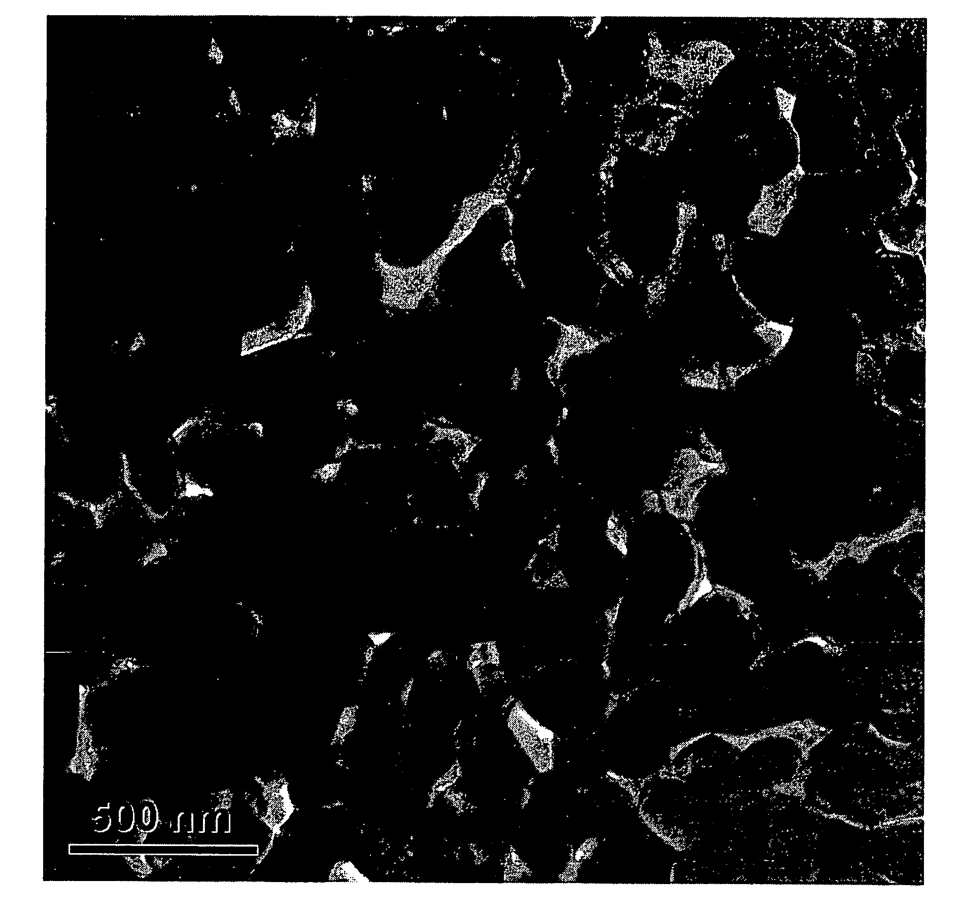
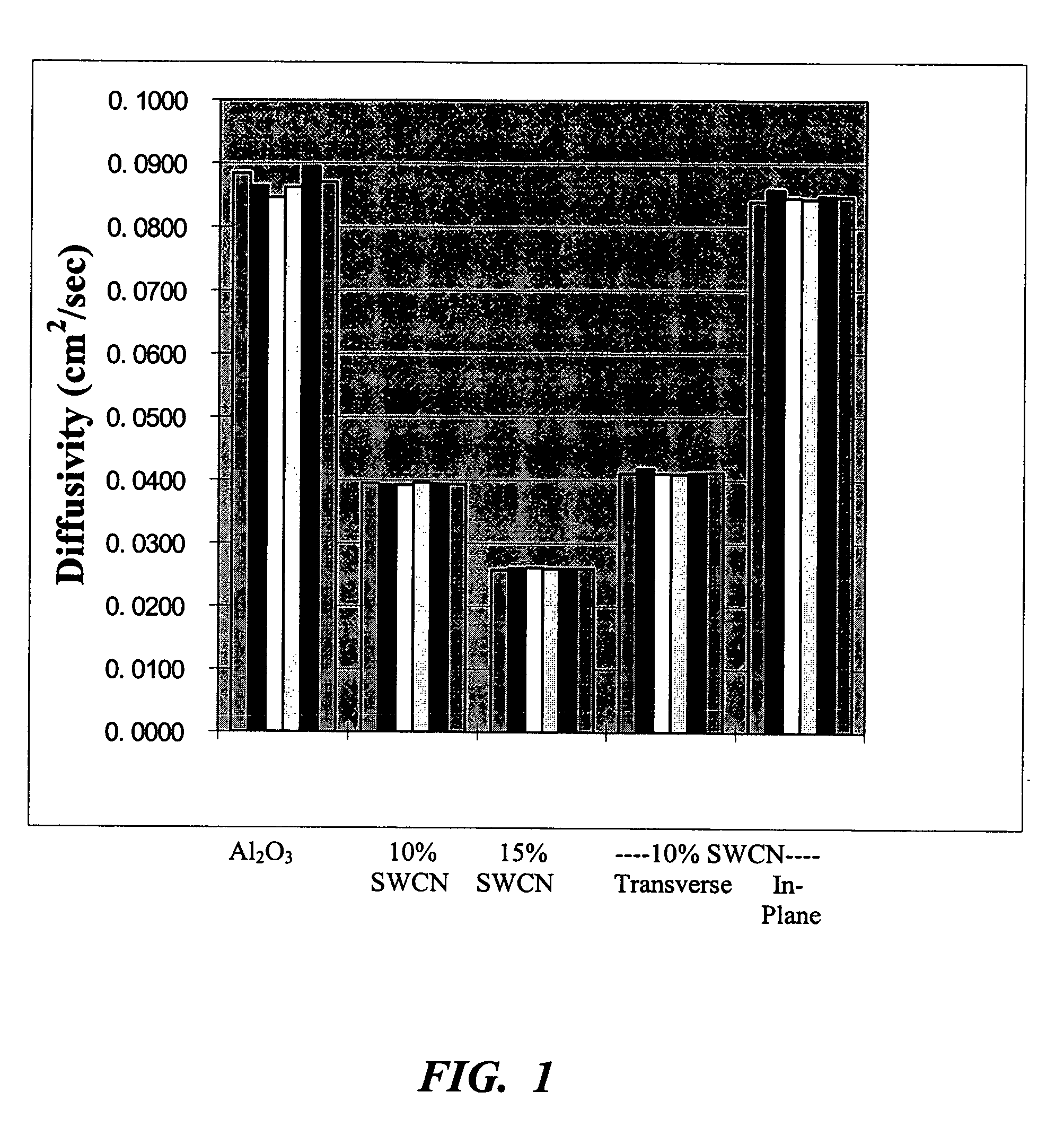
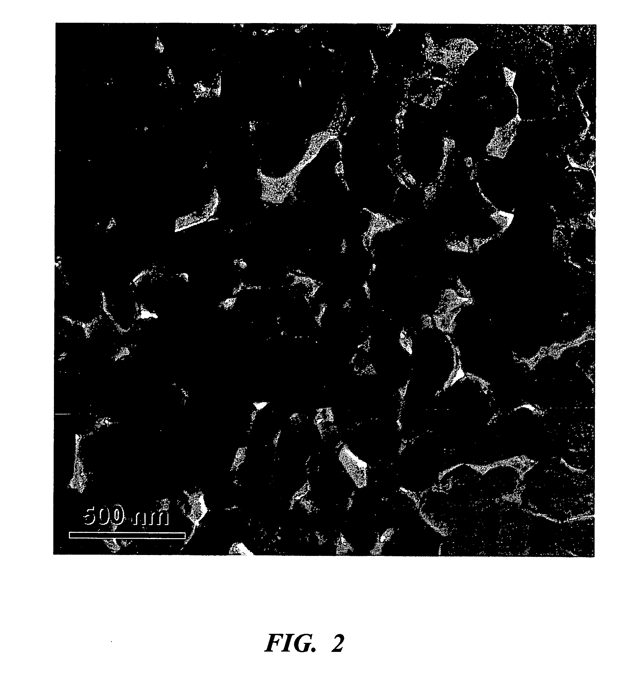
[0031]Alumina powder, consisting of 80% α-Al2O3 and 20% γ-Al2O3 with particle sizes of 300 nm (40 nm crystallite size) and 20 nm, respectively, was obtained from Baikowski International Corporation (Charlotte, N.C., USA). Gas condensation synthesized γ-Al2O3 with average particle sizes of 15 nm and 32 nm was obtained from Nanotechnologies Inc. (Austin, Tex., USA) and Nanophase Technologies Corporation (Darien, Ill., USA), respectively. Purified single-wall carbon nanotubes (SWCN) in paper form, produced by the HiPco process with more than 90% of the catalyst particles removed were obtained from Carbon Nanotechnologies (Houston, Tex., USA). The SWCN were dispersed in ethanol with the assistance of ultrasound. The alumina was then mixed with the SWCN dispersion, and the combined dispersion was sieved using a 200-mesh sieve, then ball-milled for 24 hours (still in ethanol) using zirconia milling media, and then dried to form a dry powder mixture. An alumina-SWCN mixture at 10% SWCN, by...

example 2

Materials, Equipment, and Experimental Procedures

[0041]Nanocrystalline 3Y-TZP (3 mol % yttria-stabilized tetragonal zirconia polycrystals) with an average particle size of 28 nm were obtained from Nanophase Technologies Corporation (Darien, Ill., USA). Purified single-wall carbon nanotubes, produced by the HiPco process with more than 90% of the catalyst particles removed, were obtained from Carbon Nanotechnologies (Houston, Tex., USA). The carbon nanotubes were dispersed in ethanol and the assistance of ultrasound. The 3Y-TZP nanopowder was then added to the nanotube dispersion, and the combined dispersion was sieved with a 200-mesh sieve, then ball-milled for 24 hours (in ethanol) using zirconia milling media, then dried to form a dry powder mixture. The proportions used were such that the final mixture consisted of 10% single-wall carbon nanotubes by volume and the remainder 3Y-TZP. For comparison, a sample of the same nanocrystalline 3Y-TZP was used without the carbon nanotubes....


PUM

PropertyMeasurementUnit
Temperatureaaaaaaaaaa

Abstract

Ceramic materials are converted to materials with anisotropic thermal properties, electrical properties, or both, by forming the ceramics into composites with carbon nanotubes dispersed therein and uniaxially compressing the composites in a direction in which a lower thermal or electrical conductivity is desired.

Description

CROSS REFERENCE TO RELATED APPLICATION[0001]This is a continuation-in-part of co-pending application Ser. No. 10 / 606,941, filed Jun. 26, 2003, the contents of which are incorporated herein in their entirety.STATEMENT AS TO RIGHTS TO INVENTIONS MADE UNDER FEDERALLY SPONSORED RESEARCH OR DEVELOPMENT[0002]This invention was made with Government support by Grant (or Contract) No. G-DAAD 19-00-1-0185, awarded by the U.S. Army Research Office. The Government has certain rights in this invention.BACKGROUND OF THE INVENTION[0003]1. Field of the Invention[0004]This invention resides in the field of anisotropic thermal barriers and heat-spreading materials and to materials with anisotropic electrical conductivity, and further relates to ceramics, particularly of nanocrystalline structure, and carbon nanotubes.[0005]2. Description of the Prior Art[0006]Anisotropic thermal diffusivity is a quality that is sought in materials that are used in a wide range of applications, extending from a miniat...

Claims


Application Information

Patent Timeline
IPC IPC(8): F28F13/00
CPCB82Y30/00C04B35/053C04B35/117C04B35/12C04B35/443C04B35/46C04B35/488C04B35/50C04B35/6261C04B35/62615C04B35/6264C04B35/64C04B2235/3217C04B2235/322C04B2235/3229C04B2235/5284C04B2235/5445C04B2235/5454C04B2235/666C04B2235/77C04B2235/785C04B2235/9607C09K5/14Y10S165/905
Inventor ZHAN, GUODONGKUNTZ, JOSHUA D.MUKHERJEE, AMIYA K.
Owner RGT UNIV OF CALIFORNIA
Why Eureka
Try Eureka