Methanol production process

a methanol production and process technology, applied in the field of methanol production, can solve the problems of increasing the size of process equipment, consuming up to 650 pounds of co2 /sub>per ton of methanol produced, and introducing substantial quantities of nitrogen, so as to reduce the power demand from the grid, reduce the rate, and improve the efficiency of the operation of power generating plants

Inactive Publication Date: 2009-01-08
TECH CONVERGENCE
View PDF43 Cites 7 Cited by
  • Summary
  • Abstract
  • Description
  • Claims
  • Application Information

AI Technical Summary

Benefits of technology

[0010]In a further preferred aspect of the instant invention, at least some of the electricity which is utilized in operating the electrolysis step is obtained as off-peak or valley power from a power grid. Typically, the power demand of a power grid varies throughout the day with the power demand from the grid being reduced at night when commercial and residential requirements are reduced. Not only may off-peak or valley power be obtainable at a reduced rate compared to peak demand time, but, in addition, the use of valley power may result in more efficient operation of power generating plants. For example, if it is necessary to reduce the electrical output of a power generation plant, then the efficiency of the plant may be reduced. Alternately, it may not be possible to reduce the power output of a generating plant thus resulting in the emission of greenhouse gases to produce power that is not required. Therefore, the use of valley power to run at least a portion of the electrolysis step may be highly

Problems solved by technology

For example, the process may consume up to about 650 pounds of CO2 per ton of methanol produced.
This results in the introduction of substantial quantities of nitrogen.
Not only does this result in the need to increase the size of the process equipment to have the same through put of methanol, but it also req

Method used


Image

  • Methanol production process
  • Methanol production process
  • Methanol production process

Examples


Embodiment Construction

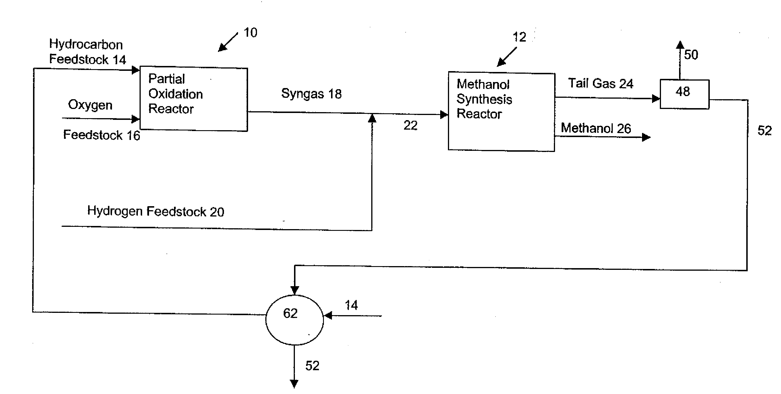
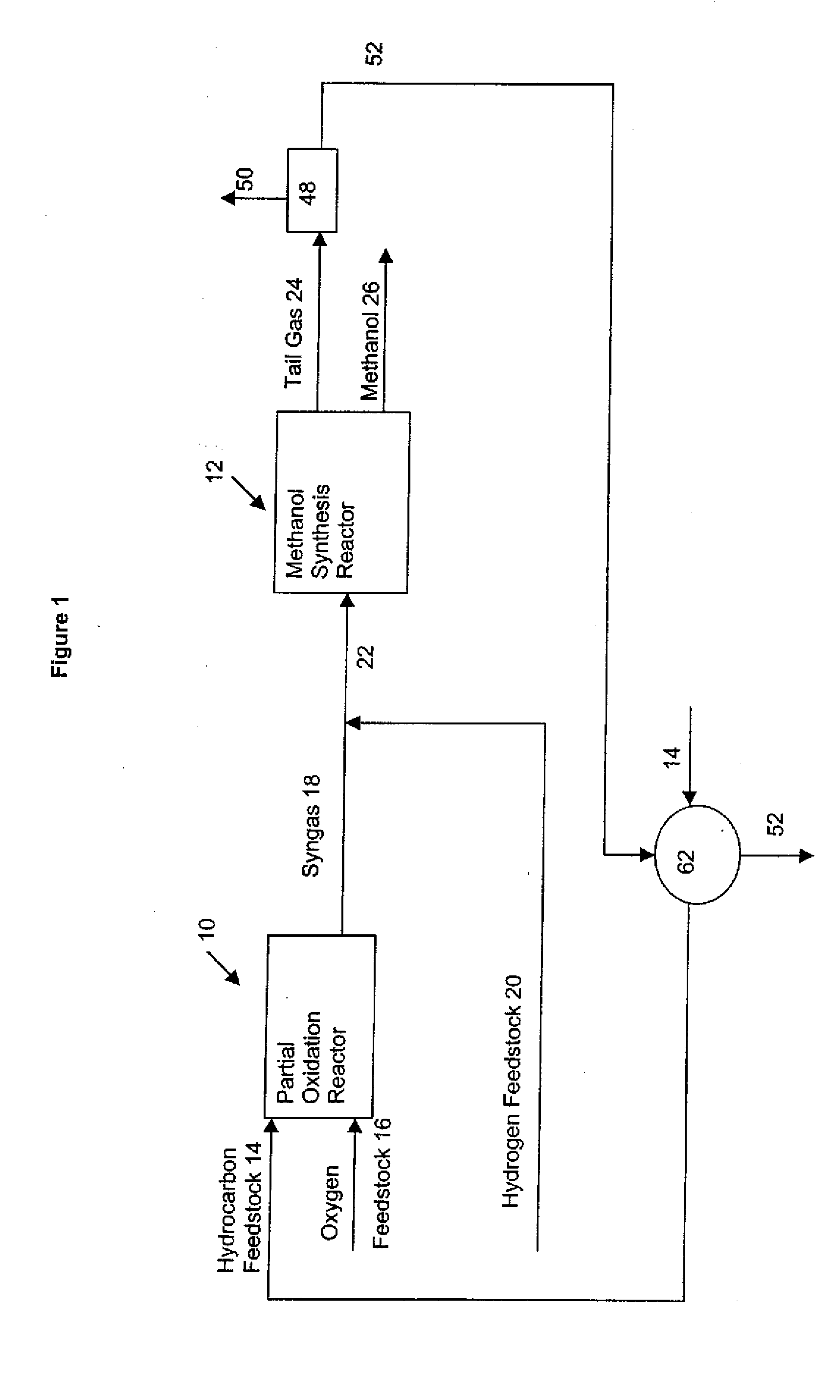
[0075]As shown in FIG. 1, according to a preferred embodiment of the instant invention, the process comprises partial oxidation reactor 10 and methanol synthesis reactor 12. Hydrocarbon feedstock 14 and oxygen feedstock 16 are fed to partial oxidation reactor 10 to produce synthesis gas 18. Hydrogen feedstock 20 is combined with synthesis gas 18 to produce synthesis gas 22 wherein the stoichiometric balance has been adjusted. The adjusted synthesis gas 22 is fed to methanol synthesis reactor 12 to produce tail gas 24 and methanol 26.

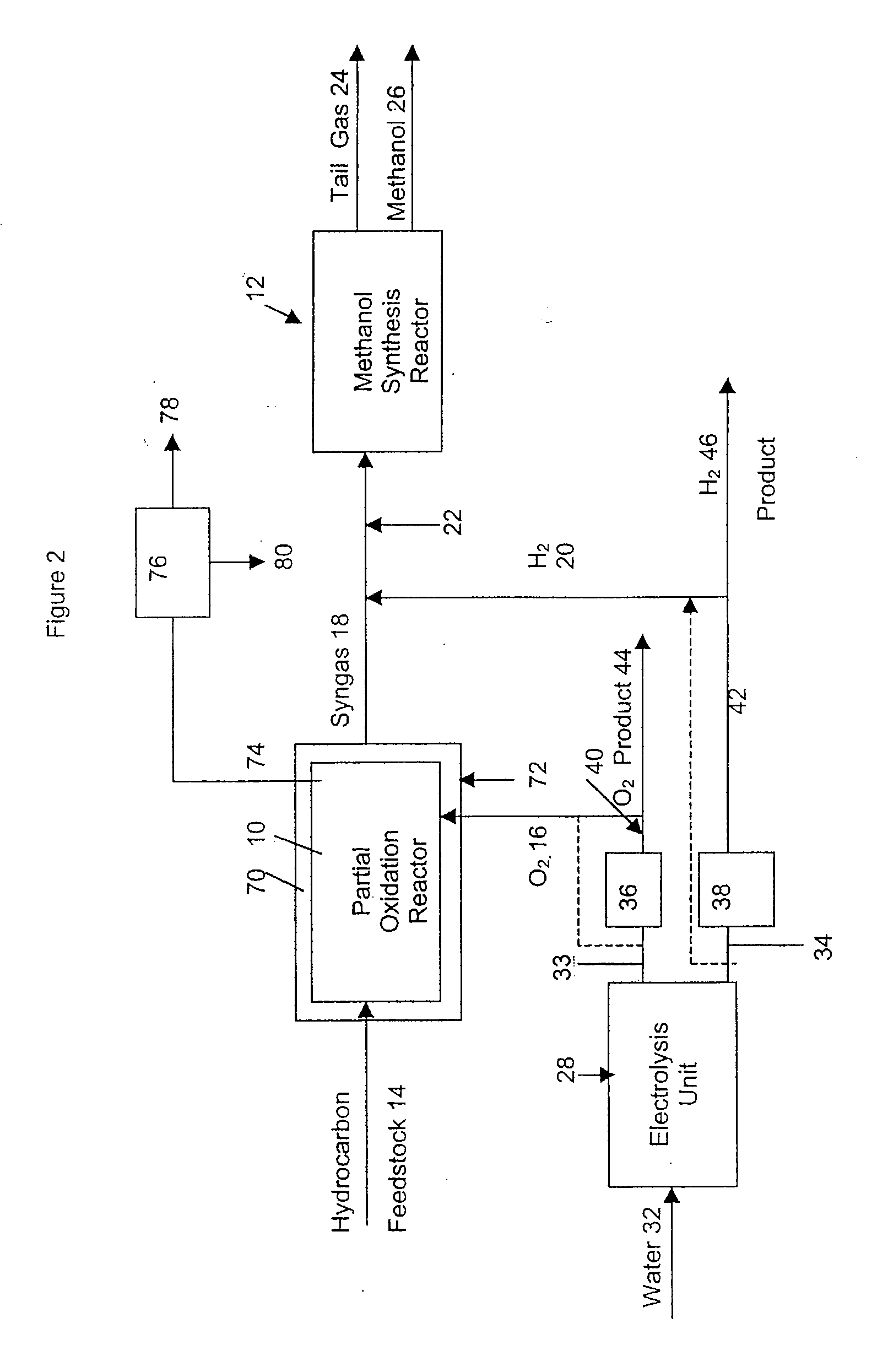
[0076]In steam reformation processes, steam is added to a reformer. Further, the hydrocarbon feedstock fed to the stream reformer may be humidified (which provides a further source of water). Overall, the process gas streams contain substantial quantities of water and the methanol produced typically is treated such as by distillation to reduce the water content of the methanol. In accordance with one embodiment of the instant process a hydrogen gas strea...


PUM

PropertyMeasurementUnit
Weightaaaaaaaaaa
Ratioaaaaaaaaaa
Mole fractionaaaaaaaaaa

Abstract

A process for the production of methanol comprises feeding an amount of a hydrocarbon feedstock and an amount of an oxygen feedstock to a partial oxidation reactor to produce a partial oxidation reactor effluent comprising hydrogen, carbon monoxide and carbon dioxide; adding an amount of a hydrogen feedstock to the partial oxidation reactor effluent to produce a synthesis gas stream having a predetermined ratio of hydrogen to carbon monoxide; and, subjecting the synthesis gas stream to methanol synthesis to produce a methanol product stream and a tail gas stream wherein reformation is not used to provide hydrogen as a product. Reformation may be used to consume hydrogen so that carbon dioxide preferably obtained as a by product of another process so that the instant process becomes effectively a temporary carbon sink to convert carbon dioxide, which would otherwise be released to the atmosphere, to a stored carbon source.

Description

[0001]This application is a continuation application of U.S. patent application Ser. No. 10 / 798,312 filed on Mar. 12, 2004 which is a continuation-in-part of U.S. Pat. No. 6,736,955 filed on Nov. 2, 2001, which is allowed.FIELD OF THE INVENTION[0002]This invention relates to a method of methanol production having reduced emission of carbon dioxide.BACKGROUND OF THE INVENTION[0003]Methanol is a synthetic fuel which is produced from reactants which provide carbon, hydrogen and oxygen. There are various sources of each of these molecules. For example, the requisite carbon may be obtained from coal (see for example U.S. Pat. No. 4,476,249 Avery), natural gas (see for example U.S. Pat. No. 5,496,589 Fong et al.) and heavy hydrocarbons such as pitch and atmospheric and vacuum residues (see for example Canadian Patent Application No. 2,060,108 Naber). Similarly, the oxygen and hydrogen, which are combined with the carbon during the synthesis step to form methanol, may be obtained from vari...

Claims


Application Information

Patent Timeline
IPC IPC(8): C07C29/00C01B3/36C01B3/38C07C29/151F25J3/02
CPCC01B3/36C01B3/382Y02E60/366C01B2203/0205C01B2203/0233C01B2203/025C01B2203/0255C01B2203/061C01B2203/142C01B2203/84C07C29/1518F25J3/0223F25J3/0257F25J3/0271F25J2205/82F25J2245/02C07C31/04Y02P20/129Y02E60/36Y02P20/141
Inventor SHAW, JOHN M.
Owner TECH CONVERGENCE
Why Eureka
Try Eureka