Method for manufacturing solar cell and solar cell

a manufacturing method and technology for solar cells, applied in the field of manufacturing methods for solar cells and solar cells, can solve the problems achieve the effects of reducing manufacturing costs, no variation in performance, and high production yield

Inactive Publication Date: 2009-01-22
SHIN-ETSU HANDOTAI CO LTD +1
View PDF6 Cites 58 Cited by
  • Summary
  • Abstract
  • Description
  • Claims
  • Application Information

AI Technical Summary

Benefits of technology

[0036]The method for manufacturing a solar cell according to the present invention facilitates a complicated process for forming a two-stage emitter structure composed of a high-concentration diffusion layer and a low-concentration diffusion layer, such as a process for forming a diffusion mask, with the result that a manufacturing cost is reduced. In addition, since a sufficient surface concentrati...

Problems solved by technology

This facilitates a complicated process for forming a two-stage emitter structure composed of a high-concentration diffusion layer and...

Method used


Image

  • Method for manufacturing solar cell and solar cell
  • Method for manufacturing solar cell and solar cell
  • Method for manufacturing solar cell and solar cell

Examples


examples 3 and 4

[0098]A low-concentration emitter layer was formed in a region printed with a diffusion paste and a high-concentration emitter layer was formed in a region subjected to only vapor-phase diffusion in accordance with the process A or B of FIG. 5 to thereby manufacture a solar cell (Examples 3 and 4). Various characteristics of the solar cell manufactured in these examples are summarized in Table 2. Incidentally, various characteristics of the solar cell of Example 2 are added for comparative purposes. In addition, spectral sensitivity characteristics (external quantum efficiency) are shown in FIG. 7.

TABLE 2Open-Short-circuitConversioncircuitcurrent densityefficiencyFillvoltage (V)(mA / cm2)(%)factorExample 30.63436.918.50.789(Process A)Example 40.63537.218.40.778(Process B)Example 20.63136.418.30.795

[0099]Both of the samples of Examples 3 and 4 subjected to the process A or B show larger values in both of the short-circuit current and the open-circuit voltage than the sample of Example ...

examples 5 and 6

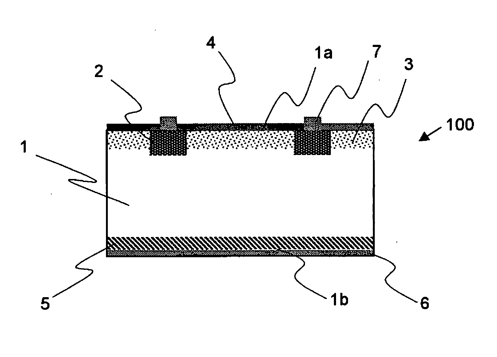
[0101]A solar cell as shown in FIGS. 6(a) and (b) was manufactured.

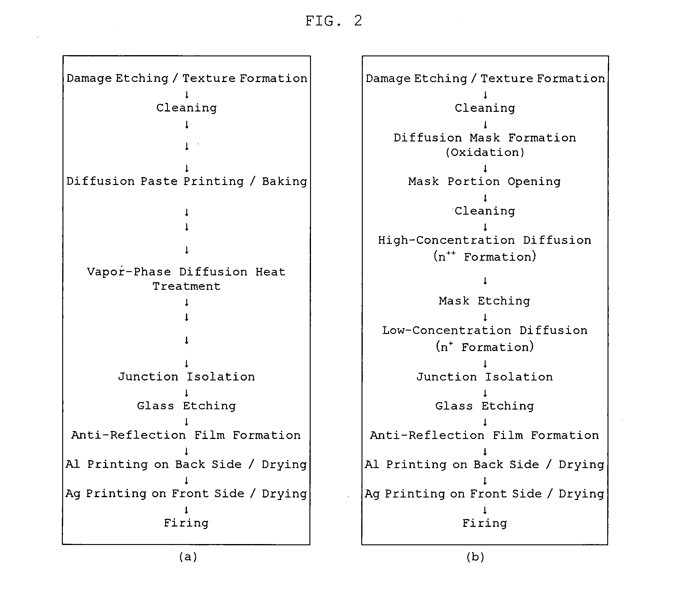
[0102]To be specific, a gallium-doped single-crystal silicon substrate having a p-type conductivity was prepared; the substrate shows crystal orientation in the direction of (100) plane, measures 15 cm per side, and has a thickness of 250 μm and a resistivity of 0.5 Ω·cm in an as-sliced state (dopant concentration of 3.26×1016 cm−3). A damaged portion was etched by about 30 μm in total on both sides with the same process as that of FIG. 2(a) to form a texture as an anti-reflection structure on the surface.

[0103]Subsequently, after the completion of cleaning the substrate, a diffusion paste was printed to a region for forming a high-concentration diffusion layer for the purpose of forming a two-stage emitter structure on the light-receiving surface side in the same way as that of FIG. 2(a) and then, the substrate was held under a POCl3 vapor-phase diffusion source atmosphere at 880° C. for 30 minutes to subject only t...


PUM


Abstract

The present invention is a method for manufacturing a solar cell by forming a pn junction in a semiconductor substrate having a first conductivity type to manufacture a solar cell, including at least: applying a first coating material containing a dopant onto the semiconductor substrate having the first conductivity type; and performing vapor-phase diffusion heat treatment to form a first diffusion layer in a region applied with the first coating material and a second diffusion layer, which is formed next to the first diffusion layer through vapor-phase diffusion, with a conductivity lower than a conductivity of the first diffusion layer at the same time, and provides a solar cell. Hence, it is possible to provide a method for manufacturing a solar cell, which can manufacture a solar cell at a low cost in a simple and easy way while suppressing surface recombination in a light-receiving surface other than an electrode region and recombination in an emitter to increase photoelectric conversion efficiency of the solar cell, and a solar cell.

Description

TECHNICAL FIELD[0001]The present invention relates to a method for manufacturing a solar cell and a solar cell, and more specifically to a method for manufacturing a solar cell at a low cost with high efficiency, and a solar cell manufactured with this method.BACKGROUND ART[0002]Nowadays, how to reduce a cost is an important issue in a method used for manufacturing a solar cell for consumer use. To that end, a method that combines a thermal diffusion method and a screen printing method has been generally employed. A detailed description thereof is given below by way of example.[0003]First, a single-crystal silicon ingot pulled up with a Czochralski (CZ) method or a polycrystalline silicon ingot manufactured through casting is sliced with a multi-wire process to thereby prepare a p-type silicon substrate. Next, slice damage on the substrate surface is removed with an alkaline solution. After that, the surface is given microscopic unevenness (texture) with the maximum height of about ...

Claims


Application Information

Patent Timeline
IPC IPC(8): H01L31/00H01L31/18H01L21/20H01L21/22
CPCH01L31/18Y02E10/547H01L31/022425H01L31/1804Y02P70/50H01L31/04H01L31/06
Inventor OHTSUKA, HIROYUKIISHIKAWA, NAOKITAKAHASHI, MASATOSHI
Owner SHIN-ETSU HANDOTAI CO LTD
Why Eureka
Try Eureka