Ultra low volume fluid delivery system using a centrifugal radial compressor and method thereof

a technology of centrifugal radial compressor and low-volume fluid, which is applied in the direction of liquid fuel engine, positive-displacement liquid engine, separation process, etc., can solve the problems of increased fuel cost and expenses, dangerous spraying conditions, and increased costs, so as to reduce contact and moving parts, energy saving, and efficient conversion

Inactive Publication Date: 2009-01-29
ADAPCO
View PDF63 Cites 13 Cited by
  • Summary
  • Abstract
  • Description
  • Claims
  • Application Information

AI Technical Summary

Benefits of technology

[0009]Radial compressors have many advantages when compared with traditional positive-displacement compressors. Among the advantages, radial compressors have fewer contacting and moving parts, and are energy efficient (radial compressors are typically 50 to 85% efficient in converting input energy to output pressure and air flow compared to 30 to 50% efficiency for positive-displacement compressors, also radial compressors are capable of pressure ranges up to 25 psi (pressure ranges of 4 to 10 psi are preferred to gain maximum efficiency), and provide a greater airflow than a similarly sized positive-displacement compressor. They produce less vibration and harmonic transmission than typical positive displacement compressors and are quieter in energy conversion to pressure and flow of the fluids being utilized. In an idealized sense, the radial compressor achieves a pressure rise and corresponding air flow by adding kinetic-energy/velocity to a continuous uninterrupted air flow entering the impeller. This kinetic energy is then converted to an increase in static pressure by slowing the air flow through a diffuser.
[0010]The use of a radial compressor enhances and boosts the efficiency of the spraying process compared to the use of many positive-displacement compressors found in the prior art when applied to targeted portions of the ambient environment, and particularly one for the efficient spraying of selected fluid droplets, such as (wi

Problems solved by technology

The use of thermal smoke generators, particularly when mounted on motorized vehicles, can often create visual obstructions and lead to dangerous spraying conditions, especially in residential areas.
In addition, the application of the gaseous smoke can be inefficient, uneven, requires large amounts of petroleum products such as diesel or kerosene as the carrier that are harmful to the environment, and can be poorly targeted due to the influence of ambient environmental and weather conditions, such as wind, topography, etc. . . . Such inefficiencies in the application process also result in increased costs in the form of fuel costs and expenses, as well as operator expenses to employ spraying equipment at low speeds over large geographic areas.
However, the Ultra Low Volume blowing equipment can produce a significant amount of undesirable emissions and comprise a number of components which need to be maintained and/or calibrated, such as pumps, meters, flow controls, and filtering devices.
In this regard, the expense of such equipment is often

Method used


Image

  • Ultra low volume fluid delivery system using a centrifugal radial compressor and method thereof
  • Ultra low volume fluid delivery system using a centrifugal radial compressor and method thereof
  • Ultra low volume fluid delivery system using a centrifugal radial compressor and method thereof

Examples


Embodiment Construction

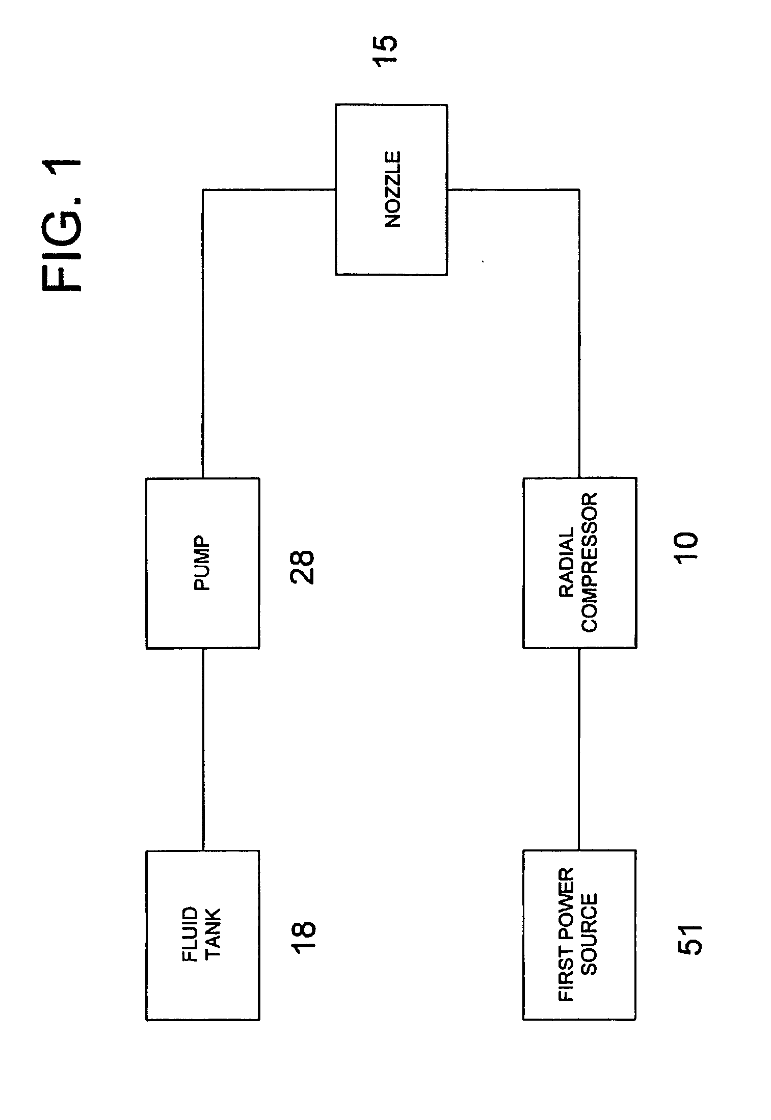
[0020]FIG. 1 depicts one embodiment of the fluid delivery system. A first power source 51 provides power to operate a radial compressor 10. The radial compressor 10 directs air flow to a nozzle 15 where it combines with fluid from the fluid tank 18 pumped to the nozzle 15 by a fluid pump 28.

[0021]FIG. 2 depicts one embodiment of the fluid delivery system. The first power source 51 operates a second power source 52. The second power source 52 provides a means for torque-speed conversion. This can be accomplished by using, among others, a transmission, gearing reduction / increase, or using different size pulleys on the output shaft of the first power source and input shaft of the radial compressor. Depending on the specifications of the first power source 51 and the radial compressor 10, the second power source 52 can reduce the output RPM from the first power source 51 to a more forceful output to the radial compressor 10, or the second power source 52 can increase the output RPM from...


PUM

PropertyMeasurementUnit
Pressureaaaaaaaaaa
Poweraaaaaaaaaa
Flow rateaaaaaaaaaa

Abstract

A fluid delivery system and method is disclosed for the application of fluids to a region using a centrifugal radial compressor.

Description

PRIORITY[0001]The present invention claims priority to provisional patent application 60 / 942,732, filed on Jun. 8, 2007, the contents of which are entirely incorporated by reference for all purposes.FIELD OF INVENTION[0002]The present invention relates generally to improved devices, systems, and methods for applying fluids, liquids, and atomized liquid / gas to desired regions and more particularly to devices, systems, and methods adapted for applying fluids, liquids, and atomized liquid / gas and using a radial compressor. It is contemplated that the present invention would provide increased utility, improvements, and enhanced operational and cost efficiencies spraying, dissemination, and application of fluids, liquids, and atomized liquid / gas mixtures for a number of purposes such as: insect control / eradication, agricultural spraying and enhancement of fruit, citrus, vegetable, horticultural, and the growing of other agricultural or commodities, pesticide applications, medicinal or me...

Claims


Application Information

Patent Timeline
IPC IPC(8): E03B5/00B67D5/52B67D7/70
CPCF04D29/705A01M7/0014Y10T137/86035Y10T137/0318Y10T137/86131
Inventor DORENDORF, BRUCEHELLER, LARRY D.DOUGLAS, JOHN T.
Owner ADAPCO
Why Eureka
Try Eureka