[0018]The advantageous effects of the incineration furnace according to the present invention are as follows. The waste is blown into the furnace
hearth in a foggy or a boiling form by the feeding device. Thus, the waste can be contacted with hot gas sufficiently, and distributed uniformly in the furnace
hearth and combusted completely therein. The combustion ratio of the waste can achieve as high as 95-97% and the combustion temperature in the incineration furnace can reach as high as 1100-1300° C. Thus, the poisonous chemicals can be decomposed at a high temperature into nontoxic and odorless
flue gas free of environmental pollution before exiting and dioxins can be degraded completely. Furthermore, the
thermal energy of the high temperature
flue gas generated during the incineration can be utilized comprehensively, for example, 1
ton purified p-
phthalic acid residues is incinerated to produce
thermal energy corresponding to that produced from combusting 1.3-1.5 tons coals. Thus, the waste is turned into
usable material. When the combustion temperature in the furnace hearth cannot meet the requirements of
environmental protection regulations, it can be increased rapidly to meet the requirements by adding oil through the oil spout to promote combustion. Thus, the poisonous chemicals in the waste can be decomposed into nontoxic and odorless high temperature
flue gas free of environmental pollution and dioxins can be degraded completely.
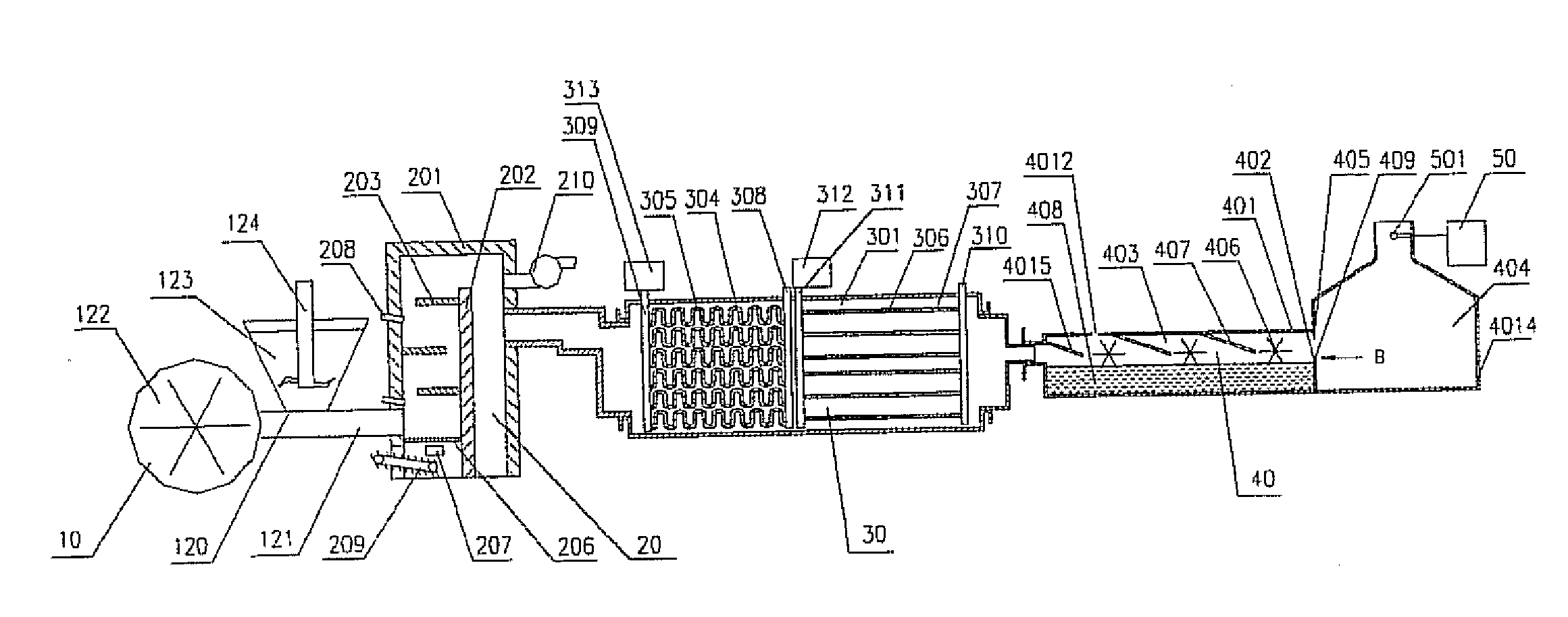
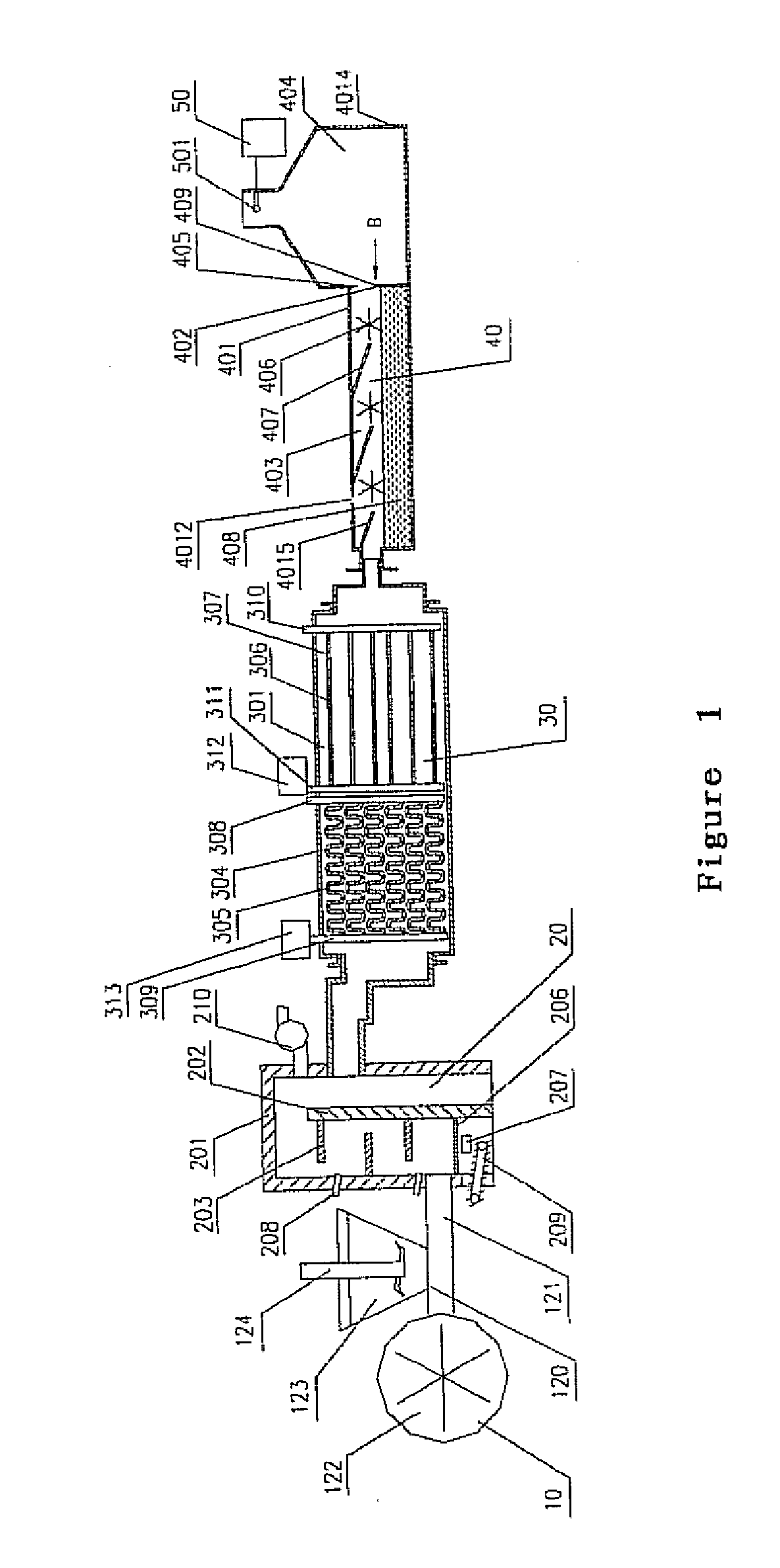
[0019]The flue
gas quenching device has a flue gas inlet and a flue gas outlet. It is connected to a steam boiler or a thermal
oil tank. The flue gas outlet of the
quenching device is connected to the flue gas inlet of the flue gas treating device. Said
quenching device has a quenching
barrel with a flue gas inlet at one end and a flue gas outlet at the other end. The quenching
barrel is divided into two segments, namely the first quenching segment wherein at least two serpentuators containing a
cooling medium, preferably thermal oil or steam are provided in parallel, and the second quenching segment wherein at least two straight tubes containing a
cooling medium, preferably water are provided in parallel. In the first quenching segment, the serpentuator is provided with an inlet and an outlet for the
cooling medium, wherein the outlet is also connected to the thermal
oil tank or the steam boiler. In the second quenching segment, the
straight tube is provided with an inlet and an outlet for the cooling medium, wherein the outlet is also connected to the steam boiler. The flow rate of the cooling medium is controlled depending on the monitoring results obtained from the online
monitoring system to achieve sufficient heat exchange between the high temperature flue gas and the cooling medium in the quenching
barrel. Thus, the high temperature flue gas is cooled below the re-forming temperature of dioxins within one second to prevent re-forming of dioxins effectively.
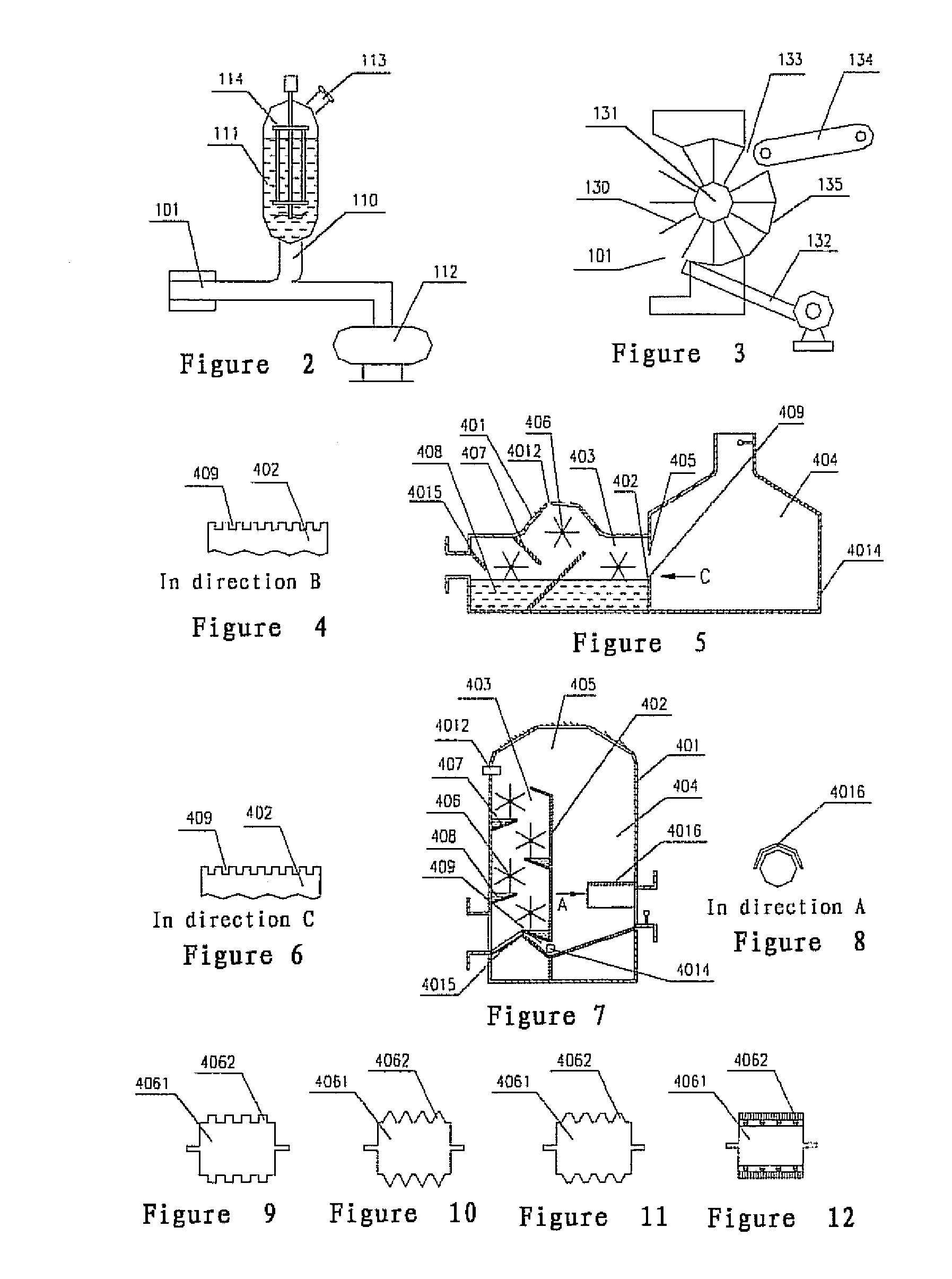
[0020]Said flue gas treating device has a gas-tight shell, wherein a partition wall dividing the shell chamber into a flue gas purification region and a liquid-
gas separation region is provided. A passage for conveying flue gas between the flue gas purification region and the liquid-
gas separation region is provided above the partition wall. The shell is provided with a gas inlet and a liquid inlet in the flue gas purification region, a gas outlet in the liquid-
gas separation region, and a liquid outlet on the bottom of the shell. On the internal wall of the shell, a gas flow baffle is provided at the gas inlet. An
impeller and a gas flow guide plate are fixed in the flue gas purification region. The gas flow guide plate and baffle are both displaced in an inclined manner with the inclination direction coinciding with the gas flow direction and the inclination angle being 10°-80°, more preferably 15°-75°, further preferably 20′-65′, most preferably 25°-60°. The number of impellers is not less than one, with each
impeller having at least one vane. The vane is provided with teeth, which can be zigzag, triangular or trapezoidal teeth unitary with the vane, or can be threads, or plastic ropes fixed on the vane. The tooth height is 1-200 mm, preferably 5-185 mm, more preferably 10-170 mm, further preferably 15-165 mm, and most preferably 20-160 mm. Purifying liquor is provided below the
impeller. Said purifying liquor is selected from the group consisting of water, basic liquor, and acidic liquor, depending on the physical and chemical properties of the waste actually treated. To ensure an effective contact between the vane and the purifying liquor, the liquor should be maintain at such a level that it contacts 1-200 mm, preferably 5-185 mm, more preferably 10-170 mm, still more preferably 15-165 mm, and most preferably 20-160 mm of the vane. An overflow passage is also provided between the flue gas purification region and the liquid-gas separation region to facilitate timely
discharge and renewal of the purifying liquor. The gas outlet of the treating device should be located on the upper part of the shell in the liquid-gas separation region to facilitate smooth exhausting of the purified flue gas in the liquid-gas separation region from the shell. Furthermore, the length of the treating device, the number of vanes, and the number and the size of the flow baffle, the flow guide plate, the flue gas purification region, and the flue gas separation region in the treating device can be adjusted depending on various factors, such as the flow rate of the flue gas, the special structure and position, and the like to assure that the purification process of the flue gas meets or exceeds the requirements of
environmental protection regulations.
[0021]Said flue gas treating device is any one selected from the group consisting of the horizontal structure shown in FIG. 1, the arched structure shown in FIG. 5, and the vertical structure shown in FIG. 7 or any variation or combination thereof. If the gas outlet is necessarily displaced on the lower part of the shell in the liquid-gas separation region due to structure requirements, an arched covering plate is needed to be provided above the gas outlet to prevent the settled purified liquid from being pushed out of the gas outlet by the exhausted gas flow.
[0023]The advantageous effects of the present invention are as follows. An appropriate
continuous feeding device is chosen depending on the forms of the waste to be treated, and the waste to be incinerated is fed into the incineration furnace continuously by the continuous feeding device. The feeding process will not cause decreased temperature in the furnace hearth and the waste is combusted in a boiling state and a layer manner in the incineration furnace. The combustion temperature in the furnace hearth can be increased rapidly by injecting oil into the furnace hearth through the oil spout to promote combustion. Thus, the temperature in the two combustion chambers of the incineration furnace achieves 1100-1300° C. to ensure sufficient combustion of the waste in the incineration furnace with the combustion ratio of the waste being as high as 95-97%. Thereby, the harmful substances contained in the waste can be decomposed through sufficient combustion. The thermal energy generated by the exhausted high temperature flue gas can be utilized sufficiently or be converted into other useful
forms of energy. Furthermore,
metal oxides and noble metals can be extracted and recovered from the furnace ashes remaining after combustion of waste and from the treating liquor in the treating device. The high temperature flue gas can be quenched below 200° C. within one second by the quenching device to prevent re-forming of dioxins in the high temperature flue gas. After the high temperature flue gas is quenched by the quenching device, it is then purified by removing harmful substances and dust contained therein through the treating device before being exhausted. The online
monitoring system monitors the temperature in the incineration furnace with continuous feeding and in the quenching device and determines whether the flue gas exhausted from the treating device meets the requirements of environmental protection regulations or not. In addition, the users can change the corresponding continuous feeding device depending on the forms of the waste to be treated. Thereby, several forms of waste can be treated without
purchasing several sets of devices. Thus, capital costs are saved for the users.

