Anode active material hybridizing carbon nanofiber for lithium secondary battery

a lithium secondary battery and active material technology, applied in the manufacturing process of electrodes, cell components, electrochemical generators, etc., can solve the problems of increasing the non-reversible capacity of the battery, improving and unable to commercially apply the anode active material prepared by amorphous carbon coating to plate type or fiber type active material,

Inactive Publication Date: 2009-02-26
KOREA KUMHO PETROCHEMICAL CO LTD
View PDF5 Cites 93 Cited by
  • Summary
  • Abstract
  • Description
  • Claims
  • Application Information

AI Technical Summary

Problems solved by technology

Because the capacity of battery depends on the charge/discharge properties of anode material, the improvement of anode active material has been a main issue in the development of secondary battery.
However, the anode active material prepared by amorphous carbon coating to plate type or fiber type of active material cannot be commercially applied, because non-reversible capacity of battery increases accordingly with the increase of reversible capacity and surface area.
Further, to obtain a uniformed metal oxide layer, a large amount of metal precursors shall be required.
On the other hand, a plate type of graphite is hard to be uniformly dispersed, which requires additional heat treatment to prepare the layer having uniformed thickness.
Since carbon nano material, such as the carbon nanotube or the carbon nanofiber has large surface area, such material has a handicap due to the high ratio of volume to weight in the electrode.
Therefore, according to the increase of amount of carbon nano material, the processibility of electrode has to be declined due to the difficulty of binding the nano material with current collector in the electrode.
Further, the high cost of carbon nano material compared to graphite is another handicap for commercializing.
However, the simple complex of carbon nano material with anode material causes another handicap, because the growth of carbon nanofibers is made in an irregular direction and carbon nanofibers have a large volume den

Method used


Image

  • Anode active material hybridizing carbon nanofiber for lithium secondary battery
  • Anode active material hybridizing carbon nanofiber for lithium secondary battery
  • Anode active material hybridizing carbon nanofiber for lithium secondary battery

Examples


preparation example 1

Preparation of Anode Active Material Hybridizing Carbon Nanofiber

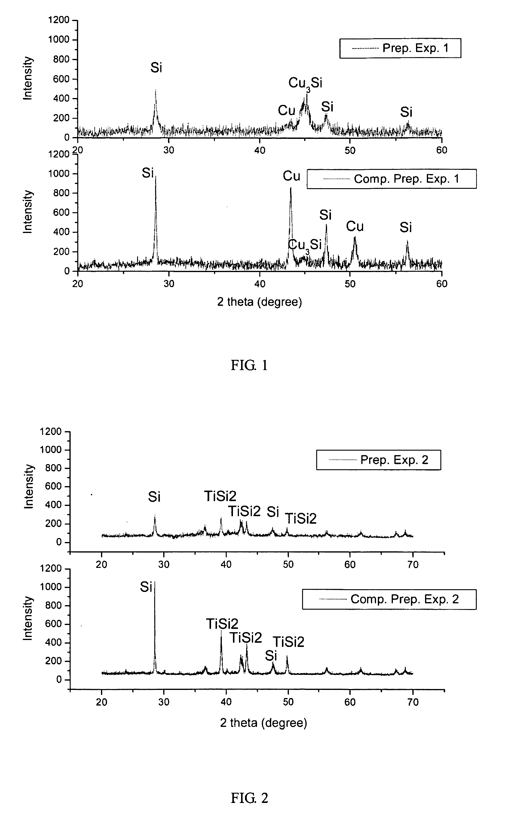
[0048]20 g of Si powder (made in China, more than 99.9% purity, #270 sieve treatment) and 20 g of Cu powder (Aldrich, more than 99% purity) are milled by Agitation Mill (ITOH, made in Japan) at argon atmosphere for 48 hours. In the presence of said powder as a support, carbon nanofiber has been grown by chemical vapor deposition method using ethylene gas and 5 wt % of Ni catalyst.

preparation example 2

Preparation of Anode Active Material Hybridizing Carbon Nanofiber

[0049]20 g of Si agglomerate (made in China, more than 99.9% purity) and 4 g of Ti rod (Aldrich, more than 99.7% purity) are melted at 1,500° C. using a melt spinning method. Then, melted product is rapidly cooled at a rate of 107 K / sec. The obtained powder is milled by SPEX Mill (Fritzch, Germany) at argon atmosphere for 4 hours. In the presence of said powder as a support, carbon nanofiber has been grown by chemical vapor deposition method using ethylene gas and 5 wt % Ni catalyst.

preparation example 3

Preparation of Anode Active Material Hybridizing Carbon Nanofiber

[0050]20 g of Si powder and 20 g of Mg powder (Aldrich, more than 99% purity) are milled by SPEX Mill (Fritzch, Germany) at argon atmosphere for 10 hours. Then, 20 wt % of petrochemical pitch (made in China, 200° C. softening point) is added and mixed. After said powder is further milled by the same manner by SPEX Mill (Fritzch, Germany) at argon atmosphere for 2 hours, the obtained powder is carbonized at 650° C. for 2 hours. In the presence of said powder as support, carbon nanofiber has been grown by chemical vapor deposition method using ethylene gas and 5 wt % Co catalyst.


PUM


Abstract

The present invention provides a composite silicon anode material hybridizing carbon nanofiber for lithium secondary battery prepared by the steps comprising: i) preparing a support made by amorphous silicon alloy after processing amorphous silicon and metal; ii) dispersing the catalyst selected from Fe, Co, Ni, Cu, Mg, Mn, Ti, Sn, Si, Zr, Zn, Ge, Pb or In on the surface of said support made by amorphous silicon alloy; and iii) growing the carbon nanofiber using a carbon source selected from carbon monoxide, methane, acetylene or ethylene on said support by a chemical vapor deposition method, wherein the amount of grown carbon nanofiber is 1˜110 wt % of the amount of said support.

Description

BACKGROUND OF THE INVENTION[0001]1. Field of the Invention[0002]The present invention relates to a composite silicon anode active material hybridizing carbon nanofiber having high capacity and high safety for lithium secondary battery. More specifically, this invention relates to a composite silicon anode active material for lithium secondary battery prepared by the steps comprising: i) preparing a support made by amorphous silicon alloy after processing amorphous silicon and metal; ii) dispersing the catalyst to the surface of said support made by amorphous silicon alloy; and iii) growing the carbon nanofiber on said support.[0003]2. Description of Prior Art[0004]In 21st century, the new paradigm of information technology capable of multi-media interactive communication has been introduced, according to the development of semiconductor which affords the small size of portable telecommunication devices, such as notebook computer, mobile and DMB phone. In accordance with the needs of...

Claims


Application Information

Patent Timeline
IPC IPC(8): H01M4/40H01M4/04H01M4/133H01M4/1393H01M4/58H01M4/583H01M10/052H01M10/36
CPCH01M4/0428H01M4/133H01M4/1393Y02E60/122H01M4/661H01M10/052H01M4/583Y02E60/10H01M4/36B82Y30/00
Inventor CHOI, IM GOOJANG, SEUNG YEONCHOI, NAMSUNSUNG, HYUN-KYUNGKIM, DONG HWANJANG, YOUNGCHANJUNG, HANGI
Owner KOREA KUMHO PETROCHEMICAL CO LTD
Why Eureka
Try Eureka