Amorphous Alloy Ribbon, Nanocrystalline Soft Magnetic Alloy and Magnetic Core Consisting of Nanocrystalline Soft Magnetic Alloy

Active Publication Date: 2009-03-12
HITACHI METALS LTD
View PDF3 Cites 39 Cited by
  • Summary
  • Abstract
  • Description
  • Claims
  • Application Information

AI Technical Summary

Benefits of technology

[0025]In the present invention, the effect is prominent even if used cheap materials which include C since a nano crystal soft magnetic alloy, a magnetic core made of a nano crystal soft magnetic alloy, and an amorphous alloy ribbon for a nano crystal soft magnetic alloy which has the excellent alternate magnetic property, the small dispersion, the excellent temporal stability in high temperature, the excellent mass productivity can be provided.
[0026]Hereafter, the present invention is explained according to embodiments, but the present invention is not limited to these.
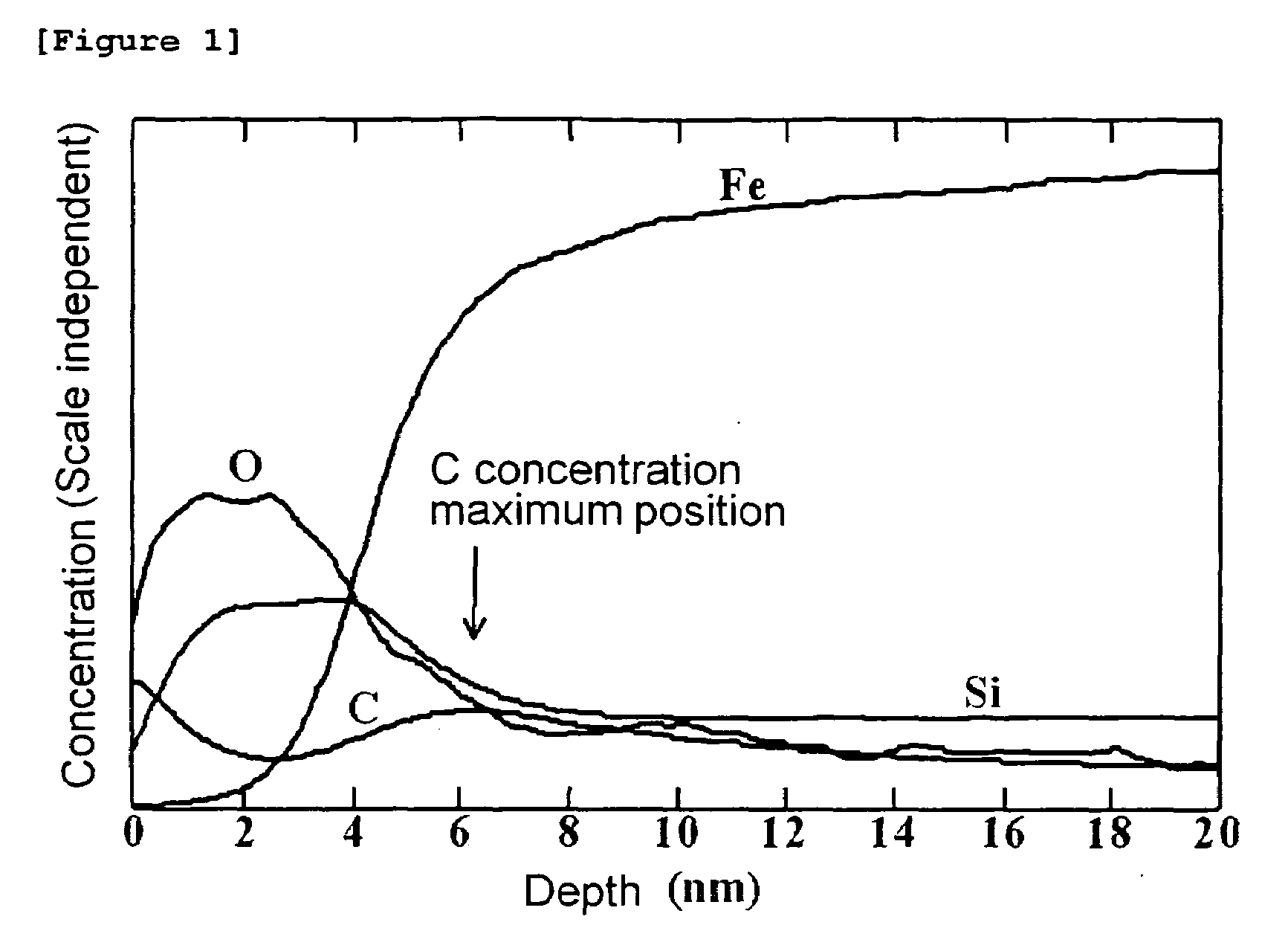
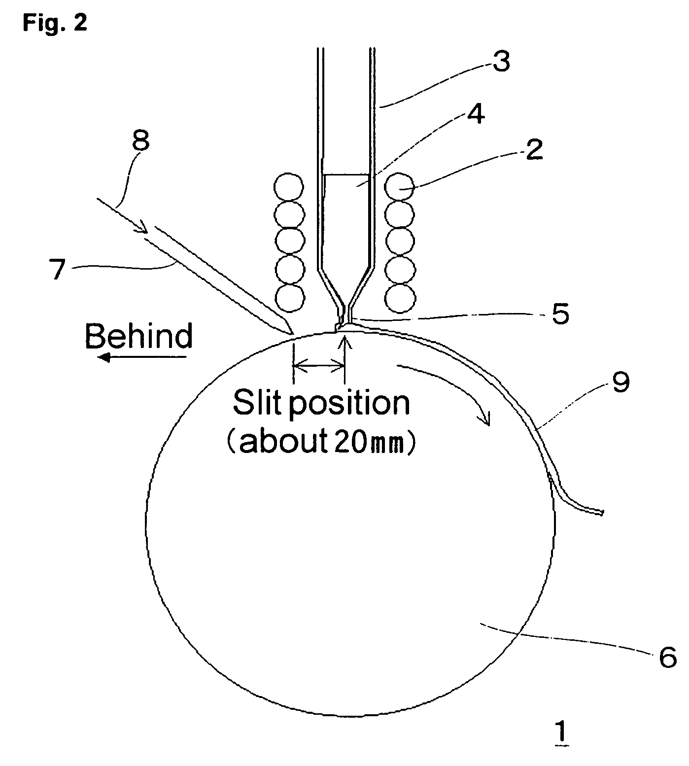
[0027]As an example of the present invention, the amorphous alloy ribbon was produced by injecting the alloy melting heated at 1300° C. of the alloy composition Febal.Cu0.9Mo3Si15.5B7.5C0.1 (atomic %) on the water cooled Cu—Cr alloy roll with an outer diameter of 400 mm rotating on the circumferential speed 30 m/s. By casting with spraying CO2 gas heated at 100° C. from a gas nozzle on Cu alloy roll from the position of about 20 mm back from the slit position of the nozzle injecting the melting, C segregation layer was formed in 2-20 nm from the surface. CO2 gas concentration around the roll surface of the nozzle tip part was 35%. The produced amorphous alloy ribbon is 50 mm in width and 20 μm in thickness. FIG. 2 is a pattern section figure of this production apparatus. In amorphous alloy ribbon production apparatus 1, alloy melting 4 heated to the aforementioned temperature in nozzle 3 with the high frequency dielectric heating by high frequency coil 2 passes through slit 5 and then injects on the surface of rotating cooling roller 6. Here, CO2 gas 8 is sprayed from gas nozzle 7 which is in the position about 20 mm behind to the rolling direction of slit 5, and amorphous alloy ribbon 9 is formed on the surface of cooling roller 6. Here, CO gas may be used instead of CO2 gas 8. Surface depth direction element concentration analysis from the roll face (surface in contact with a roll) of the produced amorphous alloy ribbon 9 was conducted in GD-OES (glow discharge luminescence surface analysis apparatus). An example of the test result is shown in FIG. 1. C concentration maximum position was set as the highest part of the C concentration except for the outermost surface part. C concentration maximum position was defined as a distance from the alloy ribbon surface estimated with equivalent SiO2. As a comparative example, the amorphous alloy ribbon with the similar alloy composition was produced in the atmosphere which CO2 gas concentration is less than 0.1% around the roll surface of a nozzle tip part. Then, the produced amorphous alloy ribbon was slit to 10 mm in width. The tape wound core was produced by winding the slit alloy ribbon with an outer diameter of 35 mm and an inner diameter of 25 mm. This tape wound core was inserted in the furnace with nitrogen gas atmosphere, and it is heated with the heating temperature rate of 7.5° C./min from room temperature to 450° C., then maintained for 20 min at 450° C., then heated with the heating temperature rate of 1.3° C./min to 530° C., then maintained for 1 hour at 530° C., then cooled with the cooling temperature rate of 1.2° C./min to 200° C., and then took out from the furnace and cooled to room temperature. The magnetic property of the sample after heat treatment were measured. C concentration of the surface depth direction was analyzed by the X-ray diffraction, the transmission electron microscopic observation, and GD-OES of the alloy with heat treatment. The average crystal grain diameter D was estimated from the crystal maximum half power band width of the X-ray diffraction. As a result of observing a microstructure by the transmission electron microscope, both samples were confirmed that the minute crystal grain with a particle diameter of about 12 nm was contained more than 70% of tissue. Table 1 shows that the alternate relative magnetic permeability μ1k at 1 kHz of the alloy after the heat treatment, the magnetic core loss Pcv at 100 kHz and 0.2 T, the relative magnetic permeability μ1k190 which measured again after maintaining at 150° C. for 190 hours, the average crystal grain diameter D of the alloy, and the C concentration maximum position of the alloy ribbon of the present invention example and the comparative example. In the alloy ribbon of the present invention example, C concentration takes maximum at the position of 6.3 nm from the roll face surface, μ1k is higher than the alloy without the C concentration maximum produced as the comparative example, the decrease of μk190 after maintaining 150° C. for 190 hours is low and the changes in characteristics with time is small. Since Pcv is also low, it can be used for the high frequency

Problems solved by technology

Since a ferrite material has a problem that the saturation flux density is low and the temperature characteristic is bad, a ferrite is magnetically saturated easily and unsuitable for the use of high power designed to become the magnetic flux density of operation large.
A silicon steel plate is a cheap material with a high magnetic flux density, but it has a problem that the magnetic core loss is large for the use o

Method used


Image

  • Amorphous Alloy Ribbon, Nanocrystalline Soft Magnetic Alloy and Magnetic Core Consisting of Nanocrystalline Soft Magnetic Alloy
  • Amorphous Alloy Ribbon, Nanocrystalline Soft Magnetic Alloy and Magnetic Core Consisting of Nanocrystalline Soft Magnetic Alloy

Examples


Example

[0032]1 amorphous alloy ribbon production apparatus[0033]2 high frequency coil[0034]3 nozzle[0035]4 alloy melting[0036]5 slit[0037]6 cooling roller[0038]7 gas nozzle[0039]8 CO2 gas[0040]9 amorphous alloy ribbon


PUM

PropertyMeasurementUnit
Fractionaaaaaaaaaa
Percent by atomaaaaaaaaaa
Nanoscale particle sizeaaaaaaaaaa

Abstract

Even if produced from a broad amorphous alloy ribbon, a nano crystal soft magnetic alloy, a magnetic core made of a nano crystal soft magnetic alloy, and the amorphous alloy ribbon for a nano crystal soft magnetic alloys which has the excellent alternate magnetic property, the small dispersion, the excellent temporal stability in high temperature, the excellent mass productivity can be provided.
An amorphous alloy ribbon, wherein the alloy composition is represented by Fe100-a-b-c-dMaSibBcCd (atomic %), 0<a≦10, 0≦b≦20, 2≦c≦20, 0<d≦2, 9≦a+b+c+d≦35, and an amorphous alloy ribbon consists of inevitable impurities, and said M is at least one element selected from Ti, V, Zr, Nb, Mo, Hf, Ta, and W, and C concentration takes maximum value at 2-20 nm depth from the surface of said amorphous alloy with equivalent SiO2.

Description

BACKGROUND OF THE INVENTION[0001]1. Field of the Invention[0002]This invention relates to an amorphous alloy ribbon for a nanocrystalline soft magnetic alloy, a nanocrystalline soft magnetic alloy made from an amorphous soft magnetic alloy ribbon, and a magnetic core made from a nanocrystalline soft magnetic alloy which is used for various transformers and various reactor choke coils, a noise suppression component, a pulse power magnetic component used for a laser power supply, an accelerator, or the like, a pulse transformer for communication, various motor magnetic cores, various dynamos, various magnetic sensors, an antenna magnetic core, various current sensors, a magnetic shield, or the like.[0003]2. Description of the Related Art[0004]As a soft magnetic material used for various transformers, various reactors, a choke coil, a noise suppression component, a laser power supply, a pulse power magnetic component for accelerators, or the like, a silicon steel, a ferrite, an amorpho...

Claims


Application Information

Patent Timeline
IPC IPC(8): H01F1/01C22C45/02
CPCB22D11/0611C21D6/00C21D8/1211H01F1/15333C22C45/02H01F1/15308H01F41/0226C21D8/1272
Inventor YOSHIZAWA, YOSHIHITOOGAWA, YUICHI
Owner HITACHI METALS LTD
Why Eureka
Try Eureka