Membrane electrode assembly and direct liquid fuel cell

a liquid fuel cell and membrane electrode technology, applied in the field of membrane electrode assembly, can solve the problems of fuel concentration cannot be increased, electrode and membrane peeling easily, energy loss, etc., and achieve the effects of improving initial operation speed, long lifespan, and less permeation of methanol

Inactive Publication Date: 2009-03-12
TOAGOSEI CO LTD
View PDF5 Cites 12 Cited by
  • Summary
  • Abstract
  • Description
  • Claims
  • Application Information

AI Technical Summary

Benefits of technology

[0021]The present invention solves the above-mentioned problems, and has been accomplished by finding that, when a non-fluorine electrolyte membrane in which the interior of pores of a porous substrate is filled with a polymer electrolyte and part of the porous substrate is preferably exposed on the surface is used as an MEA, by forming on the surface of the catalyst layer of the electrode a layer having a high polymer electrolyte content (high electrolyte content layer) as denoted by 7 in FIG. 5, contact between the polymer electrolyte within the electrolyte membrane and the polymer electrolyte within the electrode after forming an MEA as shown in FIG. 6 is improved, thus giving smooth ionic conduction and greatly reducing the time taken for the cell performance to increase.

Problems solved by technology

However, a polyperfluoroalkylsulfonic acid membrane has the problem that when it is used in a fuel cell in which a fuel solution is supplied directly to the cell, such as a direct methanol fuel cell, the methanol, etc. fuel passes through the membrane, thus causing energy loss.
Furthermore, since the membrane is swollen by the methanol, etc. fuel, and its area changes greatly, problems such as a bond between an electrode and the membrane peeling apart easily occur, and the fuel concentration cannot be increased.
Moreover, there are the economic problems that the material itself is expensive due to it containing fluorine atoms, and since the production process is complicated and the productivity is low the cost is very high.

Method used


Image

  • Membrane electrode assembly and direct liquid fuel cell
  • Membrane electrode assembly and direct liquid fuel cell
  • Membrane electrode assembly and direct liquid fuel cell

Examples


production example 1

Electrode Production Example 1

[0162]60 g of a commercial catalyst having platinum and ruthenium supported on carbon black (product name TEC61E54, manufactured by Tanaka Kikinzoku Kogyo K.K.), 20 g on a solids basis of a 5 weight % solution of a fluorine-based polymer electrolyte (product name Nafion, manufactured by DuPont) as an electrolyte, and 5 g on a solids basis of a polytetrafluoroethylene dispersion were stirred and mixed in a ball mill to give an anode catalyst ink.

[0163]This was printed on to one side of a commercial carbon paper (product name TGP-H-060, manufactured by Toray Industries, Inc.), one side of which had been coated in advance with a dispersion of carbon black in alcohol and dried so as to form a diffusion layer, and dried to give an anode electrode.

[0164]Similarly, a cathode catalyst ink was prepared using the same composition as for the anode side except that a commercial catalyst having platinum supported on carbon black (TEC10E50E, manufactured by Tanaka Ki...

example 1

Example of use of a Layer of Nafion on its own on Catalyst Layer

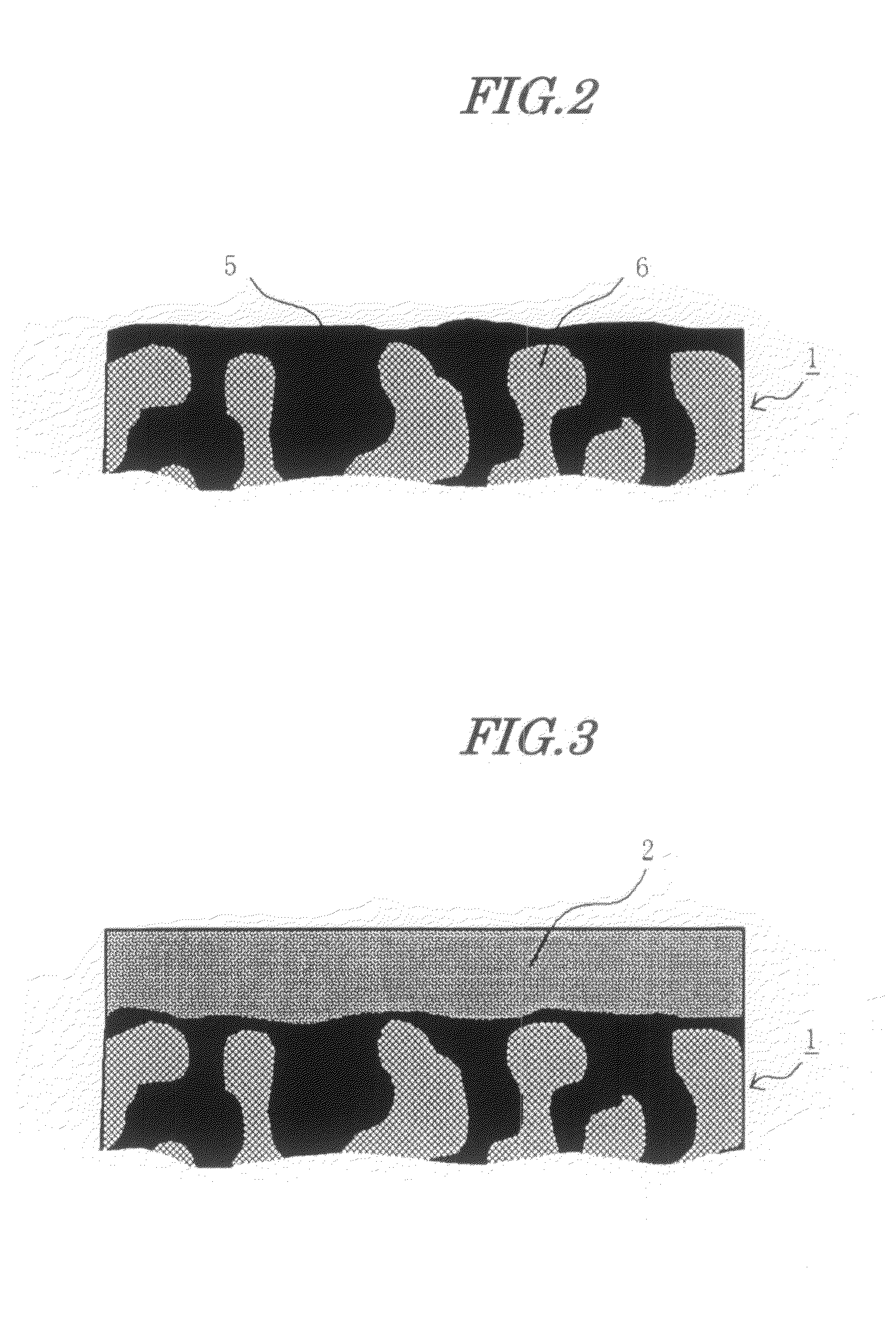
[0167]A PTFE sheet was coated with a 5 weight % solution of a commercial fluorine-based electrolyte polymer (product name Nafion, manufactured by DuPont), followed by drying to give a thin membrane.

[0168]The catalyst layers of a pair of the electrodes produced in Electrode Production Example 1 were superimposed on the above sheet, they were subjected to hot-pressing at 120° C., the PTFE sheet was removed to thus transfer the fluorine-based polymer electrolyte coating onto the catalyst layer, and they were finally heated under a nitrogen atmosphere at 180° C. for 1 hour.

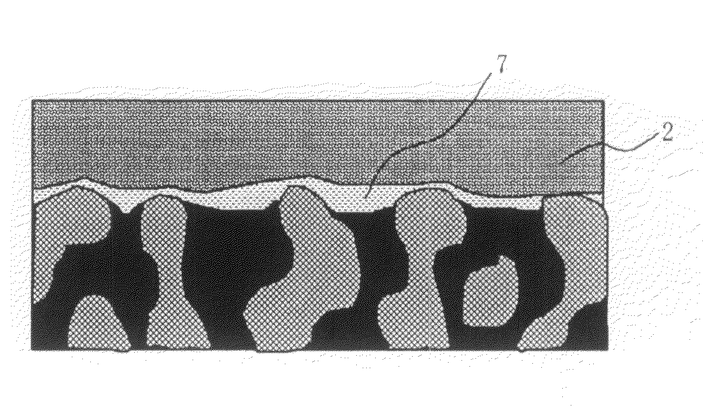
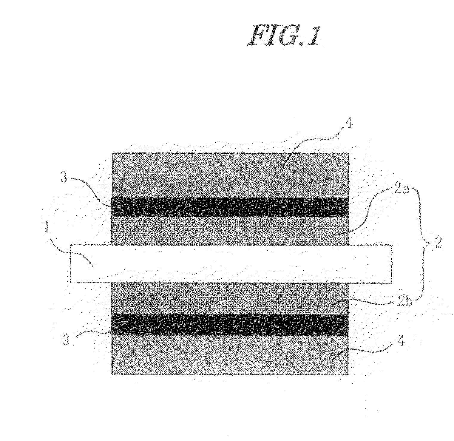
[0169]The high electrolyte content layer on the catalyst layer in this case had a polymer electrolyte proportion of 100 vol %. The hydrocarbon-based electrolyte membrane produced in Electrolyte Membrane Production Example 1 was sandwiched by this pair of electrodes and hot-pressed at 120° C., thus giving an MEA.

[0170]A direct methanol fuel cell was formed...

example 2

Example of Printing a Mixture of Nafion and Carbon on Catalyst Layer

[0172]60 g of a 5 weight % solution of a commercial fluorine-based electrolyte polymer (product name Nafion, manufactured by DuPont) and 1 g of carbon black (Ketjen Black EC, manufactured by Ketjen Black International) were mixed, and solvent was evaporated while stirring until a paste suitable for printing was obtained. This was printed on the catalyst layer of a pair of the electrodes produced in Electrode Production Example 1 by screen printing, and they were finally heated under a nitrogen atmosphere at 180° C. for 1 hour.

[0173]The high electrolyte content layer on the catalyst layer in this case had a polymer electrolyte proportion of about 75 vol %. The hydrocarbon-based electrolyte membrane produced in Electrolyte Membrane Production Example 1 was sandwiched by this pair of electrodes, an MEA was obtained in the same manner as in Example 1, and a direct methanol fuel cell was formed therefrom, and operated re...


PUM

PropertyMeasurementUnit
temperatureaaaaaaaaaa
softening temperatureaaaaaaaaaa

Abstract

To provide a membrane electrode assembly suitable for a fuel cell or an electrochemical device, and a direct methanol fuel cell employing the membrane electrode assembly.A membrane electrode assembly comprising an electrolyte membrane formed from a porous substrate having the interior of pores filled with a polymer electrolyte, and an electrode disposed on opposite faces of the electrolyte membrane and having a catalyst layer formed from a catalyst and a polymer electrolyte, the polymer electrolyte content in the catalyst layer being higher in a face where the catalyst layer is in contact with the electrolyte membrane than in other regions of the catalyst layer; and a direct methanol fuel cell employing the membrane electrode assembly.

Description

TECHNICAL FIELD[0001]The present invention relates to a membrane electrode assembly in which an electrolyte membrane and an electrode are bonded, and to a direct liquid fuel cell; more particularly, it relates to a membrane electrode assembly suitable for a fuel cell or an electrochemical device and to a direct liquid fuel cell, in particular a direct methanol fuel cell, employing the membrane electrode assembly, and to fuel cell technology.BACKGROUND ART[0002]The performance of fuel cells, which are a type of electrochemical device employing a polymer electrolyte, has improved outstandingly due to developments in electrolyte membranes and catalyst technology in recent years, and they have been attracting attention as a power source for low-pollution automobiles or as a highly efficient power generation method.[0003]This fuel cell, which employs a polymer electrolyte membrane, (hereinafter, called a ‘solid polymer fuel cell’) has a structure in which an electrode formed from a catal...

Claims


Application Information

Patent Timeline
Patent Type & Authority Applications(United States)
IPC IPC(8): H01M8/10
CPCH01M8/1051H01M8/1048H01M8/1067H01M8/1072H01M2300/0082Y02E60/523H01M4/8605H01M4/8636H01M4/8642H01M4/8657H01M8/04261H01M8/1004H01M8/1009H01M8/1011H01M8/1023H01M8/1058H01M8/04197Y02E60/50Y02P70/50H01M4/86H01M8/10
Inventor HIRAOKA, HIDEKISATO, DAIGO
Owner TOAGOSEI CO LTD
Why Eureka
Try Eureka