Polarizing plate, manufacturing method therefor, optical film and image display

Active Publication Date: 2009-04-02
NITTO DENKO CORP
View PDF0 Cites 17 Cited by
  • Summary
  • Abstract
  • Description
  • Claims
  • Application Information

AI Technical Summary

Benefits of technology

[0030]In the polarizing plate of the present invention, an active energy ray-curable adhesive is used for bonding the polarizer to the transparent protective film. Since the active energy ray-curable adhesive may be a solvent-free adhesive, the polarizer can be bonding to the transparent protective film without a drying process as used for aqueous adhesives. The active energy ray-curable adhesive allows high-speed production as compared with aqueous adhesives, because it forms an adhesive layer upon exposure to active energy rays.
[0031]The active energy ray-curable adhesive for use in the polarizing plate is preferably an electron beam-curable adhesive. Electron beam-curable adhesives can provide higher productivity than ultraviolet-ray curable adhesives. The use of an electron beam in the process of curing the adhesive used for bonding the polarizer to the transparent protective film (specifically dry lamination) can eliminate a heating process, which would otherwise be necessary for an ultraviolet-ray curing method, and thus can provide very high productivity. Electron beam-curable adhesives can further increase the durability of the polarizing plate as compared with ultraviolet-ray curable adhesives.
[0032]When an active energy ray-curable adhesive is used for bonding a polarizer to a transparent protective film as mentioned above, the adhesive strength between the polarizer and the transparent protective film could be insufficient in some cases. If the adhesive strength is insufficient, delamination between the polarizer and the protective film could occur in the process of reworking the polarizing plate, which is performed due to the improper setting position of the polarizing plate or the like. According to the present invention, an adhesion facilitating layer is provided between the transparent protective film and the adhesive layer formed with

Problems solved by technology

The presence of such a drying process in manufacture of the polarizing plate is unfavorable in view of an improvement in the productivity of the polarizing plate.
Otherwise, the aqueous adhesive cannot provide good adhesion in the resulting polarizing plate.
However, the polarizing plate obtained as described above has a problem in which its dimensions can significantly change at high temperature or at high temperature and high humidity.
However, the lamination of such a polarizer and such a transparent protective film with a

Method used


Image

  • Polarizing plate, manufacturing method therefor, optical film and image display

Examples


Example

Example 1

Adhesive: Curable Component

[0164]N-hydroxyethylacrylamide was used as an adhesive.

(Formation of Adhesion Facilitating Layer)

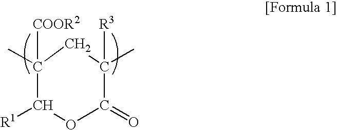
[0165]An adhesion facilitating layer-forming material (with a solid content of 11% by weight) was prepared by mixing 100 parts by weight (in terms of solid content) of a polyester skeleton-containing polymer (Superflex SF210 manufactured by Dai-Ichi Kogyo Seiyaku Co., Ltd.) and 10 parts by weight of 3-acryloxypropyltrimethoxysilane (KBM5103 manufactured by Shin-Etsu Silicone Co., Ltd.). The layer-forming material was applied to one side of a transparent protective film (the lactonized polymethyl methacrylate film) with a bar coater so as to have a thickness of 0.3 μm, and dried at 150° C. so that an adhesion facilitating layer was formed on the transparent protective film.

(Preparation of Polarizing Plate)

[0166]The adhesive was applied to the adhesion facilitating layer formed on the transparent protective film with a micro gravure coater (gravure roll:...

Example

Examples 2 to 13 and Comparative Examples 1 to 19

[0167]Polarizing plates were obtained using the process of Example 1, except that the type of the transparent protective film, the type of the adhesive (curable component), the composition of the adhesive (when any other component was used together), the type of the polymer resin for forming the adhesion facilitating layer, the type of the additive, or the content of the additive was changed as shown in Table 1.

Example

Example 14

Adhesive: Curable Component

[0168]The adhesive used was a mixture of 100 parts by weight of N-hydroxyethylacrylamide and 3 parts by weight of a photopolymerization initiator (Irgacure 127 (trade name) manufactured by Ciba Japan K.K.).

Preparation of Polarizing Plate

[0169]An adhesion facilitating layer was formed on a transparent protective film (the lactonized polymethyl methacrylate film) in the same manner as Formation of Adhesion Facilitating Layer in Example 1. The adhesive prepared above was applied to the adhesion facilitating layer with a micro-gravure coater (gravure roll #300, rotational speed 140% / line speed) so that the transparent protective film was coated with the adhesive coating with a thickness of 5 μM. The adhesive-coated transparent protective film was then laminated to both sides of the polarizer with a roller machine. An ultraviolet ray was irradiated to the side of each the laminated transparent protective films (both sides) so that a polarizing plate i...


PUM

PropertyMeasurementUnit
Percent by massaaaaaaaaaa
Adhesion strengthaaaaaaaaaa

Abstract

A polarizing plate of the present invention comprises: a polarizer; a transparent protective film placed on at least one side of the polarizer; and an adhesive layer and an adhesion facilitating layer interposed in this order from the polarizer side between the polarizer and the transparent protective film, wherein the adhesive layer is formed with an active energy ray-curable adhesive that contains a hydroxyl group-containing N-substituted amide monomer as a curable component, and the adhesion facilitating layer is formed with a polymer resin composition that contains 100 parts by weight of a polymer resin and 3 to 30 parts by weight of an organosilane compound having at least one functional group selected from an acryloyl group, a methacryloyl group, a vinyl group, and a mercapto group. The polarizing plate has good adhesion.

Description

BACKGROUND OF THE INVENTION[0001]1. Field of the Invention[0002]The present invention relates to a polarizing plate and a manufacturing method thereof. The polarizing plate may be used alone or as a part of a laminated optical film to form liquid crystal displays (LCDs), organic EL displays, CRTs, PDPs, and so on.[0003]2. Description of the Related Art[0004]The liquid crystal display market has rapidly expanded in such fields as clocks, mobile phones, PDAs, note PCs, PC monitors, DVD players, and TVs. Liquid crystal displays use liquid crystal switching to visualize changes in polarization state, and based on the display principle, they use polarizers. Particularly in TV applications and the like, there is an increasing demand for higher brightness, higher contrast, and wider viewing angle. Thus, higher transmittance, higher degree of polarization and higher color reproducibility are also demanded of polarizing plates.[0005]Iodine containing polarizer made of stretched polyvinyl alc...

Claims


Application Information

Patent Timeline
IPC IPC(8): G02B5/30B32B38/00G02B1/10
CPCB32B37/12B32B38/0008G02B5/3025B32B2310/14G02B1/105B32B2307/42G02B1/14Y10T428/31504Y10T428/31507Y10T428/31667Y10T428/31725Y10T428/3175Y10T428/31855
Inventor YAEGASHI, MASAHIROIKEDA, TETSUROUNAKANO, YUUKIAKARI, REIKOSUZUKI, MITSURU
Owner NITTO DENKO CORP
Why Eureka
Try Eureka