Laboratory plate thermal vault

a laboratory plate and thermal vault technology, applied in the field of temperature transfer devices, can solve the problems of difficult temperature control, inability to work, and large apparatus requirements of conventional methods for controlling the temperature of laboratory plates, and achieve the effects of convenient portability and amenability to work, increased productivity, and greater consistency in the established physical sta

Inactive Publication Date: 2009-04-16
COOL LAB LLC
View PDF9 Cites 14 Cited by
  • Summary
  • Abstract
  • Description
  • Claims
  • Application Information

AI Technical Summary

Benefits of technology

[0015]Another object of the instant invention is to create an enclosed environment to protect the laboratory plate from transient environmental temperature changes.
[0016]Another object of the instant invention is to act as a temperature equilibration storage system, such that a laboratory plate can be removed from one environment, and transferred to another environment at some later time without changes in the internal temperature of the laboratory plate wells.
[0017]Another object of the instant invention is to provide a temperature control device that is readily portable and amenable for work conducted in a variety of different environments (e.g. under a laboratory hood).
[0018]Another object of the invention is to provide a common surrounding environment for the wells of a laboratory plate regardless of their position in the array of plate wells. The constant environment provided by the instant invention enables greater consistency in the established physical states of each well, including temperature, thermal transfer, humidity, gas exchange, pH, static electric charge, and light exposure, based on position of the well.
[0019]Another object of the instant invention is provide increased...

Problems solved by technology

While laboratory plates are useful in holding cells and reactions separate from those in other wells, the overall design of laboratory plates makes it difficult to control the temperature.
Thus, conventional methods for controlling the temperature of laboratory plates requires a relatively large apparatus compared to the size of laboratory plates for temperature control.
Furthermore, these temperature control devices are generally not readily portable nor are these methods very quick or easy to conduct in a sterile environment (e.g. under a laboratory hood).
Although these routines are set up to maximize throughput, problems are often encountered that produce less than satisfactory conditions for conducting experimental assays.
One of the problems that can contribute to reduced productivity is what is commonly referred to in the art as “edge effects”.
The prob...

Method used


Image

  • Laboratory plate thermal vault
  • Laboratory plate thermal vault
  • Laboratory plate thermal vault

Examples


example 1

[0067]As an example, mammalian cell agar assays depend on rapid cooling of a cell suspension in molten agar so that the agar solidifies before the cells have a time to settle. In this particular application, the temperature transfer device is cooled to a desired temperature and the laboratory plate is placed on top of the stage such that the top surface of the stage comes in direct contact with the bottom of individual wells of the laboratory plate. This allows the contents of the individual wells to be cooled such that the agar solidifies before the cells have a time to settle.

[0068]Typically, the temperature transfer device of the invention is placed on ice, dry ice, liquid nitrogen or any heating or cooling device until the temperature of the temperature transfer device has reached the approximate temperature of the cooling or heating medium. The temperature transfer device can be left in contact with the cooling or heating medium or placed on a thermally insulating surface such ...

example 2

[0069]Reduction of Edge Effects in Cell Culture

[0070]A thermal vault with the sterile culture plate and plate cover seated in place would be placed into an incubator and allowed to equilibrate with the interior temperature. During this interval, cultured cells would be removed from their primary culture vessel by use of trypsin solution, transferred to a centrifuge tube, concentrated by centrifugation, and re-suspended in warm growth medium. The thermal vault with culture plate would be retrieved from the incubator and the cells to be cultured would be quickly dispensed to the appropriate wells. The plate cover would be replaced and the thermal vault encasement be placed into position. The assembly would be returned to the incubator and allowed to remain undisturbed until the cells have attached or until any other experimental way point. Due to the thermally conductive property of the stage, this method / procedure allows the culture plate to maintain a uniform well temperature across...

example 3

[0071]Reduction of Edge Effects in ELISA Assays

[0072]For reduction of edge effects in an ELISA assay, a 96-well flat bottom plate would be placed onto a thermal vault base either in a stand-alone configuration or in thermal contact with a temperature-regulation device. A standard ELISA assay would be assembled into the wells of the 96-well plate, and the plate cover replaced or the plate sealed using commonly available adhesive closure seals. The thermal vault encasement would be placed over the 96-well plate and seated into the base groove. A standard reaction time would be allowed to pass while the plate is either allowed to remain still or agitated by a common shaking device. The ELISA assay would then be completed by application of the appropriate wash steps and colorimetric reaction while the plate remains in contact with the vault base. Due to the thermally conductive property of the stage, a uniform well temperature would be maintained across the plate thereby reducing or eli...


PUM


Abstract

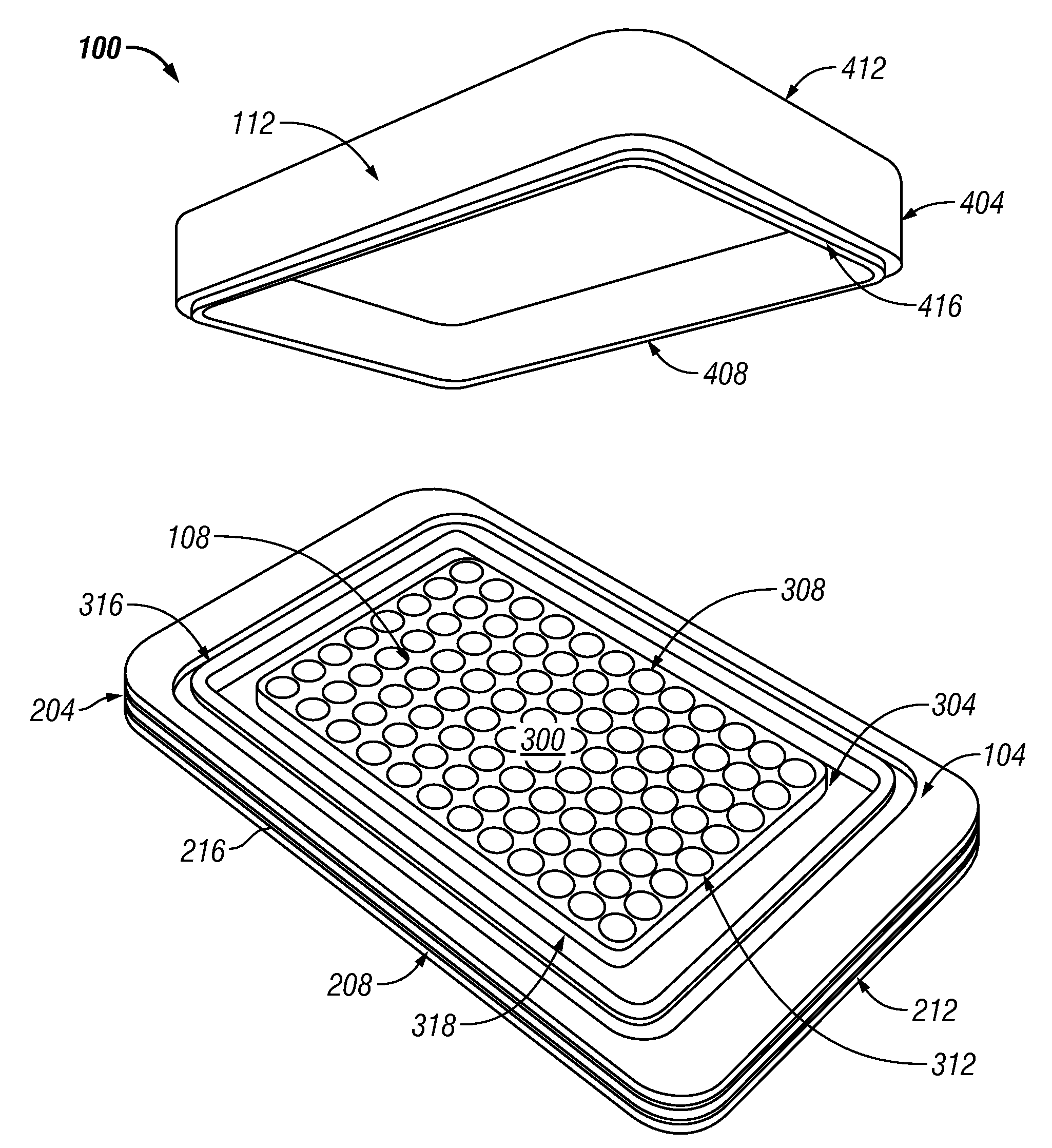
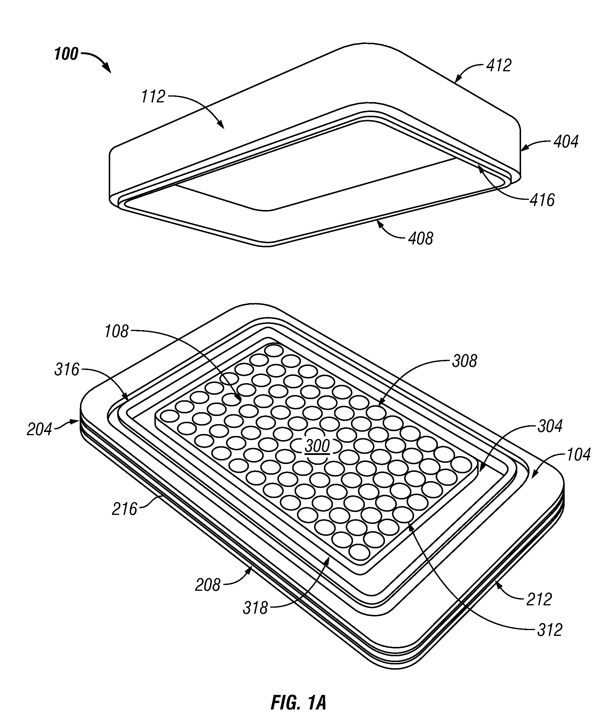
A portable temperature transfer device for transferring thermal energy to and/or from a laboratory plate is provided as well as its methods of use. The temperature transfer device comprises a base and a raised stage that comprises a thermal conductive material and an encasement that interfaces with the base to create a cavity that encloses a laboratory plate. The raised stage allows direct contact between individual wells of the laboratory plate and the temperature transfer device. The encasement completes the thermally conductive environment for the laboratory plate.

Description

CROSS-REFERENCE TO RELATED APPLICATION[0001]This application is a continuation-in-part of commonly assigned, copending U.S. patent application Ser. No. 60 / 980,167 filed Oct. 15, 2007.FIELD OF THE INVENTION[0002]The invention relates to temperature transfer devices and methods for using the same. In particular, some aspects of the temperature transfer devices are adapted to be used with various laboratory or cell culture plates.BACKGROUND OF THE INVENTION[0003]Many chemical, binding, and molecular biological reactions, as well as in vitro culture of cells or tissue, require maintaining proper conditions such as temperature and humidity. In research or laboratory settings, often laboratory or cell culture plates (hereinafter simply “laboratory plates”) are used.[0004]The laboratory plates generally comprise a plurality of wells that are designed, for example, to hold cells or tissues in culture medium; biological, experimental or production reactions; biological or chemical reaction a...

Claims


Application Information

Patent Timeline
IPC IPC(8): C12Q1/02C12M1/02C12M1/12C12N5/06B01L7/00
CPCB01L7/00B01L7/02B01L9/523B01L2300/041C12M41/18B01L2300/1805C12M23/12C12M23/44B01L2300/0829C12M41/14
Inventor EHRHARDT, ROLFSCHRYVER, BRIANSCHRYVER, JEFF
Owner COOL LAB LLC
Why Eureka
Try Eureka