Optical Recording Medium and Optical Recording Method

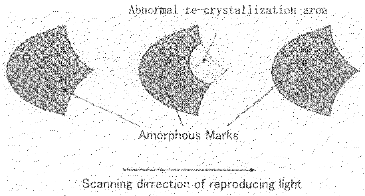
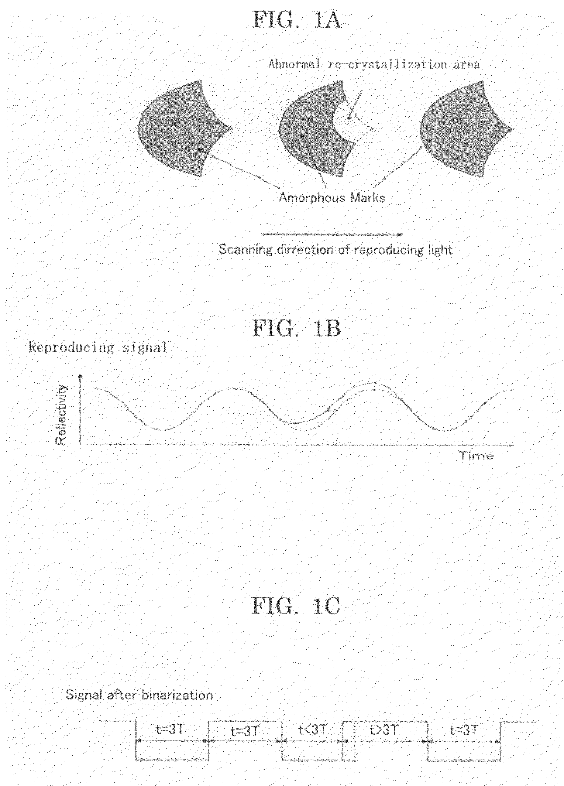
a recording medium and optical recording technology, applied in the field of high-density optical recording mediums, can solve problems such as distortion of reproducing signals, adverse effects, and errors in reproducing signals

Inactive Publication Date: 2009-05-07
RICOH KK
View PDF0 Cites 2 Cited by
  • Summary
  • Abstract
  • Description
  • Claims
  • Application Information

AI Technical Summary

Benefits of technology

[0042]The present invention is aimed at providing an optical recording medium and an optical recording method which can achieve an optical disc system which can perform a high-speed recording, wherein the optical disc system can perform a recording without problems such as error increase due to abnormal re-crystallization and jitter increase due to cross light, and a high-speed recording is possible while maintaining a backward compatibility such that a low-speed recording can be performed on the same optical recording medium in a drive for low-speed recording.
[0043]In addition, the present invention provides an optical recording medium for a high-density recording, where the optical recording medium can comply with DVD at 8×-speed or faster or Blu-ray Disc at 4×-speed or faster, and the optical recording medium includes a phase-change recording layer which is superior in re-writing performance and provides stable amorphous and crystal phases and simple initialization.

Problems solved by technology

However, it has become clear that the increase in the crystallization speed of an optical recording medium in response to the fast recording speed of DVD over 8×-speed causes various adverse effects as described below.
The first point is that a large crystal grows in an amorphous mark in the process of recording and that the apparent mark length is shorter, than intended, causing an error in reproducing.
It has been known that the abnormal crystal growth causes a distortion in the reproducing signal and enhances the error.
This error tends to increase as the recordable speed increases.
However, it is easily inferred from the principle of the phase-change recording that a high-speed recording at a low crystallization speed suppresses the speed of the crystal growth during the formation of a recording mark and widens the recording mark as an amorphous layer and that the above-mentioned problem occurs.
Therefore, it has been considered difficult to achieve the both high-speed recording and wide range of recordable speed.
In addition, in a method disclosed in Patent Literature 3, overwriting becomes difficult at a higher speed, and there is a problem that the range of recording speed is inadequate.
In this regard, the power of LD should be enhanced, and there is a problem that the LD tends to heat unnecessarily an adjacent track and crystallizes a part of the recorded amorphous mark.
The third point is the problem that a low-speed recording with recording conditions equivalent to a conventional low-speed optical recording medium is not possible.
In other words, the backward compatibility cannot be maintained.
Even though a recording over 8×-speed is achieved for DVD, it is a problem that the convenience of a user is sacrificed unless the recording is possible with a conventional drive for 8×-speed recording.
An optical disc system for higher-speed recording which does not have the problems of increase in errors due to abnormal re-crystallization and increase in jitter due to cross light and which maintains the backward compatibility that a recording in the same optical recording medium at a low speed is maintained even with a conventional drive for low-speed recording has not been achieved.
However, a favorable mark may not be formed due to insufficient power since the laser diode (LD) has a limitation in its output power.
A disadvantage of such Sb—Teδ phase is that it has a low crystallization temperature of 120° C. to 130° C. Therefore, it is necessary to introduce elements such as Ag, In and Ge to increase the crystallization temperature to 160° C. to 180° C. to improve the stability of an amorphous mark.
However, increasing the composition of Sb tends to make the initialization difficult, causing non-uniformity in reflectivity after initialization.
This increases the noise, and a favorable recording with low jitter cannot be achieved.
Also, the increase of Sb further reduces the crystallization temperature, so it cannot help but increase the quantity of additives.
The simple increase of additives also makes the initialization difficult, causing the increase in the noise, and a favorable recording with low jitter cannot be achieved.
In other words, it is difficult to obtain a recording layer with an Sb—Teδ system that satisfies a crystallization speed for high-speed recording equivalent to 8×-speed of DVD, simple initialization and preservation stability of an amorphous mark.
However, these eutectic points are around 590° C., which is higher than the eutectic point of Sb—Teδ phase system of 550° C., and the recording power may be insufficient.
Also, according to examinations by the inventors of the present invention, materials with high melting points are prone to non-uniformity of reflectivity after initialization.
Therefore, the noise is also increased after initialization after all, and a favorable recording with low jitter is difficult.
The reason is not clear, but it cannot be resolved simply by the increase in the initialization power.
However, further researches revealed that this In—Sb system had a disadvantage of low crystallization stability despite its superior stability of an amorphous phase.
The results of the preservation test indicate that the reflectivity decreases by 10% or greater, and there is a risk that the medium does not satisfy the standards.
In addition, a recording in a condition with reduced reflectivity results in severely degraded jitter, and a favorable recording cannot be performed.
They of course do not consider the compliance to a high-speed recording of DVD and Blu-ray Disc, and they neither disclose nor indicate any specific detail.

Method used


Image

  • Optical Recording Medium and Optical Recording Method
  • Optical Recording Medium and Optical Recording Method
  • Optical Recording Medium and Optical Recording Method

Examples


examples a-1 to a-9

AND COMPARATIVE EXAMPLES A-1 TO A-6

[0233]A disc substrate made of a polycarbonate resin having a diameter of 12 cm, a thickness of 0.6 mm and a groove with a track pitch of 0.74 μm was dehydrated at a high temperature. On the substrate, a first protective layer, a recording layer, a second protective layer, an anti-sulfuration layer and a reflective layer were sequentially deposited in this order, and a phase change optical recording medium was prepared.

[0234]More specifically, with a sputtering apparatus, DVD Sprinter manufactured by Unaxis, Ltd., a first protective layer having a thickness of 65 nm was deposited with a ZnS—SiO2 target having a molar ratio of 8 to 2 was deposited on the substrate. On the first protective layer, a recording layer having a thickness of 16 nm was deposited with an alloy target having a composition on an atom basis shown in Table 1 under sputtering conditions of argon gas pressure of 0.4 Pa (3×10⁻³ Torr) and RF power of 300 mW. On the recording layer, ...

example a-10

[0244]On the phase-change optical recording media prepared in Examples A-1 to A-4, high-speed recordings were performed at 12×-speed (about 42 m / s) with the 1T write strategy shown in FIG. 7A, and the width of the recording marks were monitored. Here, the pattern of the 1T write strategy and the reproducing conditions were equivalent to those in Example 1.

[0245]It was found that the modulation exceeded 0.45 when the write power was 30 mW or greater and that the width of a recording mark was about 75% of the 0.28-μm groove. The reflectivity was 0.25, and the R×M exceeded 0.11. The jitter was 10%.

[0246]From the conditions above, the write power was increased. When the write power was 36 mW, the jitter was 9.3%, reflectivity was 0.25 and R×M was 0.14. The width of a recording mark was about 90% of the groove width.

[0247]The write power was further increased. When the write power was 39 mW, the mark width was almost equivalent to or a little less than the groove width. The mark didn't s...

example a-11

[0248]Optical recording media were prepared in the same manner as Example 1 except that the thicknesses of the recording layers and the first protective layers were adjusted such that the reflectivity of the media were 18%, 22%, 24% and 30%, respectively. For each optical recording medium, a recording was performed at 6×-speed with the 2T write strategy, and the modulation was adjusted by varying the write power. Furthermore, the error rate in reproducing was evaluated. The results are shown in FIG. 18.

[0249]The results in FIG. 18 indicate that the modulation decreases with decreasing write power. The vertical dotted line in FIG. 18 indicates the modulation, i.e. 0.6, 0.5, 0.46 and 0.37, for the reflectivity of 18%, 22%, 24% and 30%, respectively, with which the value of R×M is 0.11.

[0250]The results in FIG. 18 also indicate that the error rates abruptly increased when the value of R×M was near 0.11. When the modulation was small, the error rate started increasing with the modulatio...


PUM

PropertyMeasurementUnit
wavelengthaaaaaaaaaa
transition linear velocityaaaaaaaaaa

Abstract

An optical recording method to record information with a mark length recording method, where an amorphous mark and a crystal space are recorded only in the groove of a substrate having a guide groove, with the temporal length of the mark and the space of nT (T denotes a reference clock period; n denotes a natural number). The space is formed at least by an erase pulse of power Pe; all the marks of 4T or longer are formed by a multi pulse alternatively irradiating a heating pulse of power Pw and a cooling pulse of power Pb while Pw>Pb; and the Pe and the Pw satisfy the following relations:0.15≦Pe / Pw≦0.4, and0.4≦τw / (τw+τb)≦0.8,where τw denotes the sum of the length of the heating pulses, and τb denotes the sum of the length of the cooling pulses.

Description

TECHNICAL FIELD[0001]The present invention relates to a high-density optical recording medium having a phase-change recording layer such as DVD+RW, DVD-RW, BD-RE, HD DVD RW and a recording method for the optical recording medium.BACKGROUND ART[0002]The increase in the capacity of electric information has been prominent, and optical recording media which enable faster recording have been desired since a recording apparatus handling larger volume data requires more time for recording. In particular, the speeding up of disk-shaped optical recording media has been increasing since the rotational speed can increase the recording and reproducing speeds. Among such optical recording media, ones having a simple recording mechanism that recording takes place only with an intensity modulation of a light irradiated during recording have become popular since they enable the price reduction of the optical recording medium and recording apparatus. An optical recording medium for recording only in...

Claims


Application Information

Patent Timeline
Patent Type & Authority Applications(United States)
IPC IPC(8): G11B7/00G11B7/125G11B7/243G11B7/2433
CPCG11B7/0062G11B7/1263G11B7/2433G11B2007/24314G11B2007/2431G11B2007/24312G11B2007/24304G11B7/0045G11B7/126
Inventor ITO, KAZUNORIHIBINO, EIKOTAKADA, MIKIKODEGUCHI, HIROSHIOHKURA, HIROKOMIURA, HIROSHI
Owner RICOH KK
Why Eureka
Try Eureka