Method of metallizing solar cell conductors by electroplating with minimal attack on underlying materials of construction

a solar cell and conductor technology, applied in the direction of optics, coatings, optical elements, etc., can solve the problems of materials easily being chemically attacked by immersion in conventional electroplating solutions, the cost of commercial implementation of dry deposition methods is high, and the effect of improving the conductivity and efficiency of solar cells

Inactive Publication Date: 2009-05-14
TECHNIC INC
View PDF18 Cites 39 Cited by
  • Summary
  • Abstract
  • Description
  • Claims
  • Application Information

AI Technical Summary

Benefits of technology

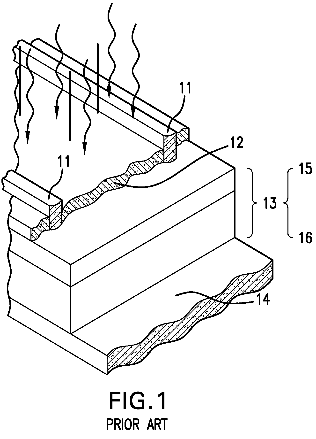
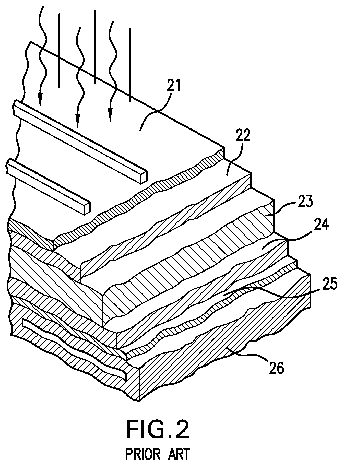
[0009]The present invention now satisfies the needs of the industry by applying additional layers of metals, such as silver, nickel, copper and tin, by electroplating upon an initial conductive layer, typically a conductive paste, to improve the conductivity and efficiency of the solar cell.
[0010]In one embodiment, a metallized solar cell having enhanced electrical conductivity or electrical efficiency is provided. This cell comprises a substrate that has electroplatable conductors comprising an initial conductive metallic layer on the substrate and non-electroplatable portions; and one or more additional metal layers upon the initial conductive solar cell material to improve conductivity and increase electron or current flow, as well as reduce, minimize or prevent corrosion or oxidation of the initial conductive solar cell conductor material. Optionally, an organic protective coating is included to minimize oxidation or other surface reactions from occurring on the conductive metallic layer or additional metal layer(s). The initial conductive layer is typically a silver paste comprising greater than 50% to 100% by weight silver and having a thickness of about 1 to 30 microns, or it can be a deposited metal layer, while the one or more additional metal layers comprise silver, nickel, copper, tin, indium, gallium, selenide or alloys or combinations thereof. The initial conductive layer is applied by a metallization method comprising conductive metal paste screening, physical or chemical vapor deposition, or electroless or electrolytic plating depending upon the preference of the manufacturer.
[0012]Yet another embodiment of the invention is a method of enhancing the electrical conductivity or electrical efficiency of a solar cell which comprises providing electroplated metal layers that are significantly free of residual stress on a solar cell substrate thereon to form more substantial current carrying metal deposits, wherein the residual stress of the metal layers is no more than about 12,000 psi to bonding of the layers and minimize loss of electrical connectivity. The residual stress in the electroplated metal layers is no more than about 8000 to 9000 psi.

Problems solved by technology

Conventionally, the metal layers are applied through “dry” deposition methods such as physical vapor deposition (PVD) and chemical vapor deposition (CVD), but these dry deposition methods require very specialized equipment and materials which are costly to implement commercially.
Furthermore, dry deposition processes are very time consuming especially when applying relatively thick metallic layers, e.g., several microns which are required for the conductor metallization operation.
One drawback of the use of the construction materials in the CIGS method, however, is that such materials can easily be chemically attacked by immersion in conventional electroplating solutions.
Certain solutions negatively affect the adhesion of the conductor to the substrate and result in “lift-offs” which break the electrical connectivity of the cell, resulting in failures of the solar cell.
High stress values can cause the deposit to contract upon itself during or immediately after plating, which can initiate adhesion failures and lift-offs, as residual stress is relieved through the contraction process.
Currently, most conductive pastes used to form the conductors are porous containing typically 30-40% vacancies or open spaces, and these detrimentally affect the conductivity of the conductor to reduce solar cell efficiency.

Method used


Image

  • Method of metallizing solar cell conductors by electroplating  with minimal attack on underlying  materials of construction
  • Method of metallizing solar cell conductors by electroplating  with minimal attack on underlying  materials of construction
  • Method of metallizing solar cell conductors by electroplating  with minimal attack on underlying  materials of construction

Examples


example 2

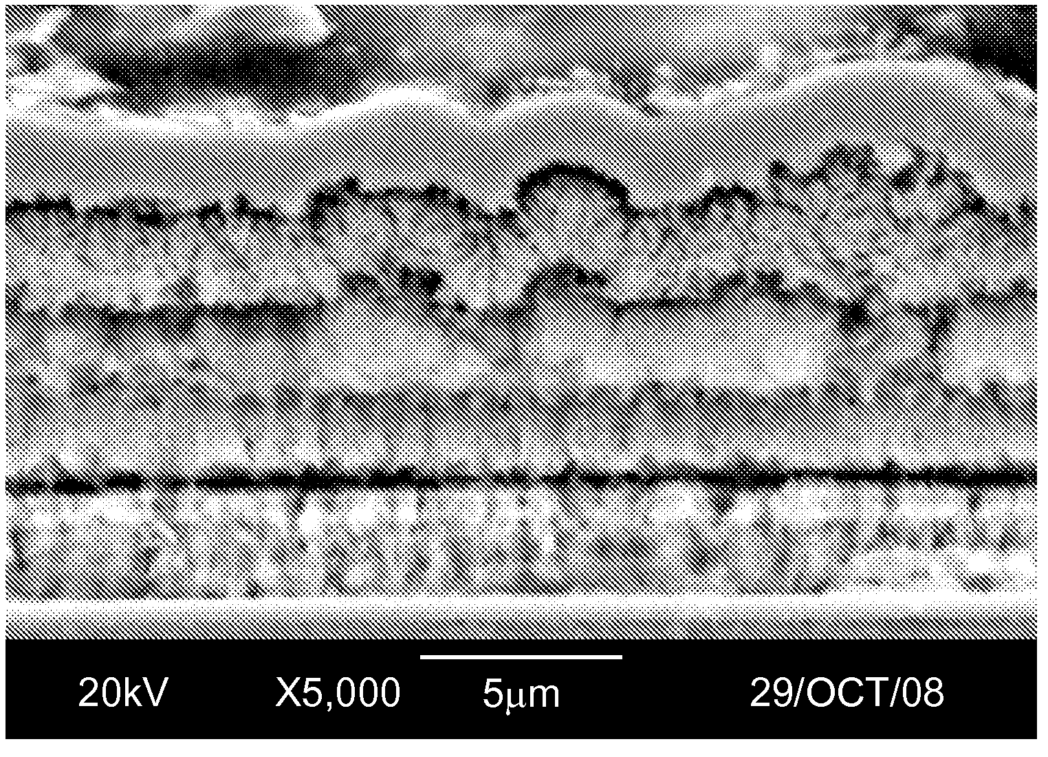
[0041]Silver was electroplated from a commercial silver non-cyanide electrolyte which is also free of organic sulfonic acids (Technisol AG from Technic Inc.) onto a silicon solar cell substrate which had been previously metallized and fired with silver conductive paste. Silver was plated at 1 A / dm2 for a period of time sufficient to obtain an average of 5 μm silver deposit thickness. The residual stress value of this deposit was approximately 4000 psi. The metallized solar cell was then subjected to heat and humidity aging at 85° C. / 85% RH for 1000 hrs, after which a simple tape test for adhesion was performed. This sample passed the tape test as none of the silver deposit or conductive paste was removed during the tape removal.

example 3

[0042]Silver was electroplated from a commercial silver non-cyanide electrolyte which is also free of organic sulfonic acids (Technisol AG from Technic Inc.) onto a silicon solar cell substrate which had been previously metallized and fired with silver conductive paste. Silver was plated at 1 A / dm2 for a period of time sufficient to obtain an average of 5 μm silver deposit thickness. The residual stress value of this deposit was approximately 4000 psi. The metallized solar cell was then further processed through a post-treatment chemistry (Tarniban KS from Technic Inc.) which forms a thin, benign, protective organic coating on the silver deposit. The metallized solar cell with protective organic coating was then subjected to heat and humidity aging at 85° C. / 85% RH for 1000 hrs, after which a simple tape test for adhesion was performed. This sample passed the tape test as none of the silver deposit or conductive paste was removed during the tape removal.

example 6

[0045]Nickel was electroplated from a commercial electrolyte which is free of organic sulfonic acids (Technisol Nickel LB from Technic Inc.) onto a silicon solar cell substrate which had been previously metallized and fired with silver conductive paste, and plated with silver using the process listed in Example 2. Nickel was plated at 1 A / dm2 for a period of time sufficient to obtain an average of 5-7 μm nickel deposit thickness. The deposit was then subjected to the heat and humidity aging at 85 C / 85% RH for 1000 hrs, after which a simple tape test for adhesion was performed. This sample passed the tape test as none of the conductor metal was removed during the tape removal.


PUM

PropertyMeasurementUnit
thicknessaaaaaaaaaa
thicknessaaaaaaaaaa
thicknessaaaaaaaaaa

Abstract

The invention relates to a metallized solar cell and the method of making thereof that includes depositing a metal or metals such as silver, nickel, copper, tin, indium, gallium, or selenium or their alloys on solar cells in a manner to form more substantial and robust electrical contacts that can carry current more efficiently and effectively or to provide the active layers required to convert sunlight into electricity. These deposits also protect the underlying metallic materials from corrosion, oxidation or other environmental changes that would deleteriously affect the electrical performance of the cell. The invention also relates to the use of specialized electroplating chemistries that minimize residual stress and / or are free of organic sulfonic acids to minimize chemical attack on solar cell substrates or prior metallizations that include organic and / or inorganic binders or related materials for depositing the initial metallic portions of the cell.

Description

CROSS-REFERENCE TO RELATED APPLICATIONS[0001]This application claims the benefit of U.S. application 60 / 986,971 filed Nov. 9, 2007, the entire content of which is expressly incorporated herein by reference thereto.FIELD OF INVENTION[0002]The present invention relates to a method for enhancing solar cell performance by improving electrical conductivity and electron flow and providing overall protection from chemical attack to the underlying materials of construction of the solar cell panel. In particular, the invention contemplates depositing a metal or metals such as silver, nickel, copper, tin, indium, gallium, or selenium or their alloys on solar cells in a manner to form more substantial and robust electrical contacts that can carry current more efficiently and effectively or to provide the active layers required to convert sunlight into electricity. These deposits also protect the underlying metallic materials from corrosion, oxidation or other environmental changes that would d...

Claims


Application Information

Patent Timeline
Patent Type & Authority Applications(United States)
IPC IPC(8): H01L31/00C25D7/12
CPCC25D5/34C25D5/48Y02E10/50H01L31/022425C25D7/08
Inventor SCHETTY, III, ROBERT A.
Owner TECHNIC INC
Why Eureka
Try Eureka