Polymer coatings containing drug powder of controlled morphology

a technology of controlled morphology and polymer coating, which is applied in the direction of prosthesis, immunological disorders, metabolism disorders, etc., can solve the problems of poor bioavailability, pharmaceutical or biological agents, and difficulty in achieving uniform coatings

Active Publication Date: 2009-05-14
View PDF99 Cites 74 Cited by
  • Summary
  • Abstract
  • Description
  • Claims
  • Application Information

AI Technical Summary

Problems solved by technology

Although these processes have been used to produce satisfactory coatings, there are drawbacks associated therewith.
For example it is often difficult to achieve coatings of uniform thicknesses and prevent the occurrence of defects (e.g. bare spots).
Also, in many processes, multiple coating steps are frequently necessary, usually requiring drying between or after the coating steps.
Another disadvantage of most conventional methods is that many pharmaceutical or biological agents, once deposited onto a substrate, suffer from poor bioavailability, reduced shelf life, low in vivo stability or uncontrollable elution rates, often attributable to poor control of the morphology and / or secondary structure of the agent.
Pharmaceutical agents present significant morphology control challenges using existing spray coating techniques, which conventionally involve a solution containing the pharmaceutical agents being spayed onto a substrate.
Lack of or low degree of crystallinity of the spray coated agent can lead to decreased shelf life and too rapid drug elution.
While the use of conventional solvent-based spray coating techniques may successfully result in the deposition of a biological agent upon a substrate, it will often result in the loss of at least some of the secondary, tertiary and / or quaternary structure of the agent and therefore a corresponding loss in activity.
For example, many proteins lose activity when formulated in carrier matrices as a result of the processing methods.
Conventional solvent-based spray coating processes are also hampered by inefficiencies related to collection of the coating constituents onto the substrate and the consistency of the final coating.
As the size of the substrate decreases, and as the mechanical complexity increases, it grows increasingly difficult to uniformly coat all surfaces of a substrate.

Method used


Image

  • Polymer coatings containing drug powder of controlled morphology
  • Polymer coatings containing drug powder of controlled morphology
  • Polymer coatings containing drug powder of controlled morphology

Examples


example 1

Process Equipment

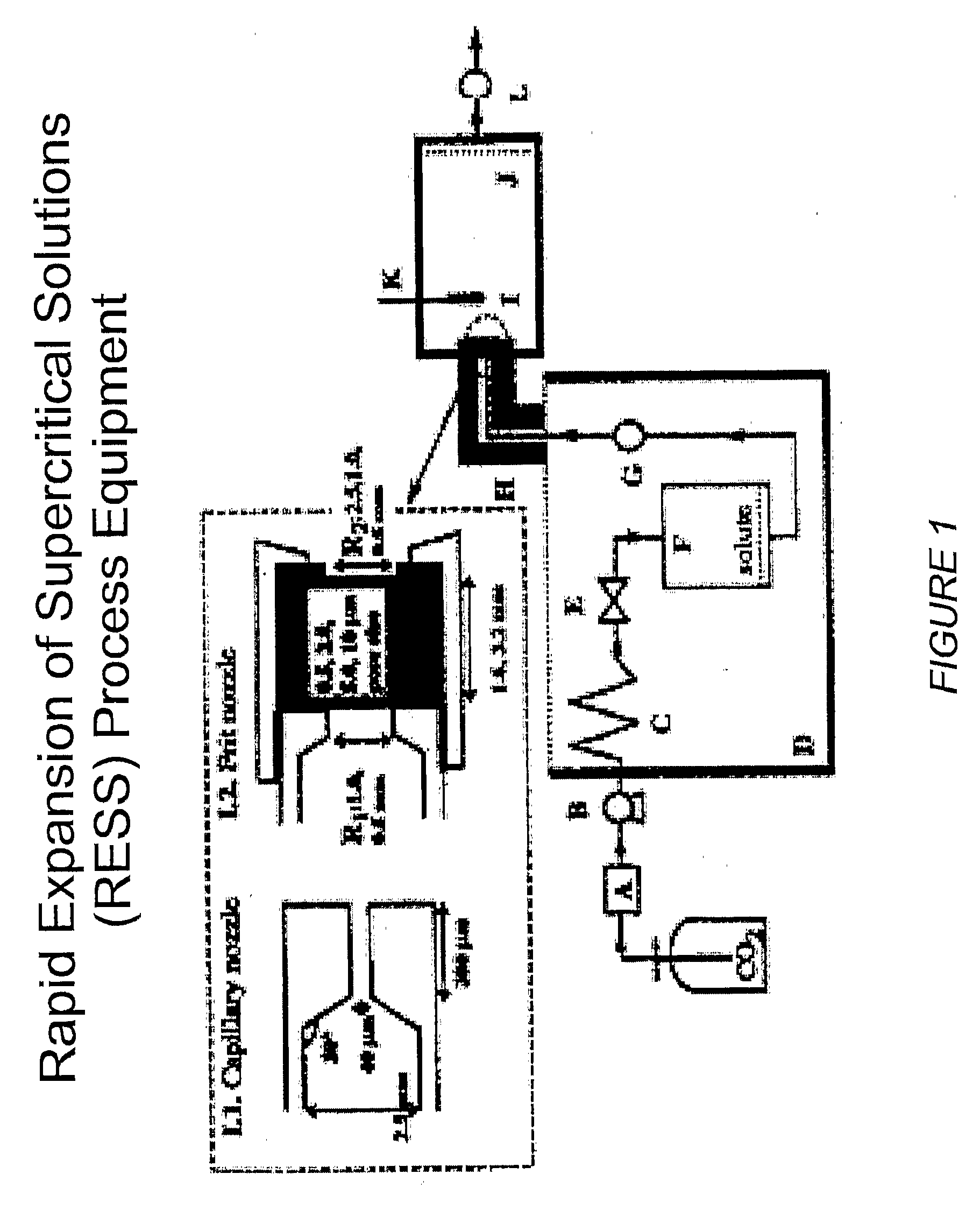
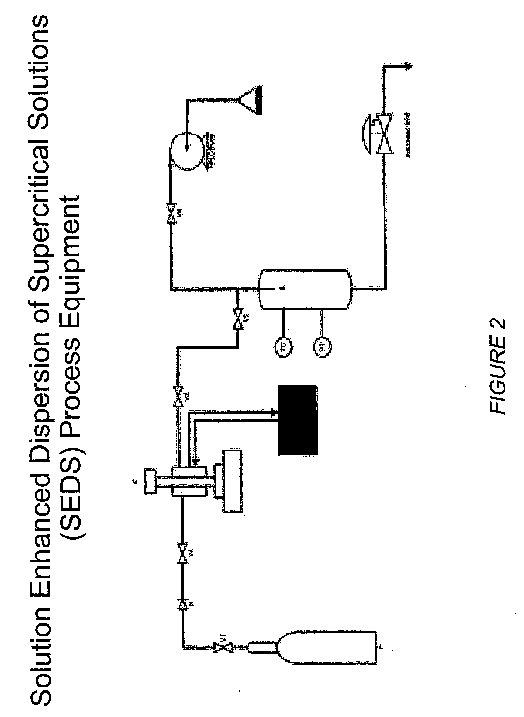
[0209]The RESS process equipment used in the present studies is depicted in FIG. 1. This is a common design for a RESS apparatus see C. Domingo et al, Journal of Supercritical Fluids 10, 39-55 (1997). The SEDS equipment used in the present studies is depicted in FIGS. 2 and 10. FIG. 2 shows a common SEDS apparatus and FIG. 10 shows a SEDS apparatus using a two-nozzle design with electrostatic capture of the sprayed particles. The nozzle orifice size can be used to control the particle size. FIG. 3 depicts the nozzle design for the SEDS equipment shown in FIGS. 2 and 10. FIG. 4 shows the FTIR spectra of a representative small molecule medically therapeutic agent, two polymers and the mixture of the components. IR stretches specific to each molecule are identified and labeled. FIG. 5 shows implantable medical devices coated with pharmaceutical agent and polymer under various sintering conditions. FIG. 6 shows the infrared spectra of the 3-component coating before and ...

example 2

General Spray Coating 1

[0210]A solution containing a therapeutic chemical compound that is saturated in a solvent or supersaturated in a solvent is sprayed at a flow rate sufficient to achieve flow into a chamber of known volume pressurized above ambient pressure and containing a medical device substrate. The system temperature is held constant or allowed to vary so that any number of points in the phase diagrams of the solution or mixture or any of its individual components can be mapped in pressure-temperature, volume-pressure or pressure-volume space constituting liquid, gas or supercritical CO2 conditions. CO2 in any single phase or combination of phases flows through the chamber at a mass flow rate of 5 gm / min to some multiple of this flow rate. After a period of time ranging from seconds to minutes or hours have elapsed, the solute and solvent flow that is a solution of the therapeutic compound and suitable solvent for the chosen solute or solutes cease but CO2 flow continues ...

example 3

Spray Coating 2

[0211]A solution of equal parts of one solvent and another miscible solvent containing therapeutic chemical compound is prepared so that compound is not saturated. This solution is sprayed at a known flow rate ranging from 1 mL / min to 100 mL / min into a chamber of known volume and pressurized above ambient pressure. The system temperature is maintained at a constant level or allowed to vary so that any number of points in the phase diagrams of the solution or mixture or any of its individual components can be mapped in pressure-temperature, volume-pressure or pressure-volume space. CO2 flows through the chamber at a known flow rate. Spraying is stopped after a period of time, but CO2 flow continues for an additional period of time sufficient to ensure that the chamber volume has been turned over or replaced a sufficient number of times to remove any residual solvent or co-solvent from the chamber after which the pressure is reduced to atmospheric pressure. As in the ab...


PUM

PropertyMeasurementUnit
thicknessaaaaaaaaaa
particle sizeaaaaaaaaaa
flow rateaaaaaaaaaa

Abstract

A method for depositing a coating comprising a polymer and pharmaceutical agent on a substrate, comprising the following steps: discharging at least one pharmaceutical agent in a therapeutically desirable morphology in dry powder form through a first orifice; discharging at least one polymer in dry powder form through a second orifice; depositing the polymer and / or pharmaceutical particles onto said substrate, wherein an electrical potential is maintained between the substrate and the pharmaceutical and / or polymer particles, thereby forming said coating; and sintering said coating under conditions that do not substantially modify the morphology of said pharmaceutical agent.

Description

CROSS-REFERENCE[0001]This application claims the benefit of U.S. Provisional Application Nos. 60 / 699,650 filed Jul. 15, 2005; 60 / 752,338 filed Dec. 20, 2005; 60 / 771,066 filed Feb. 7, 2006; 60 / 771,725 filed Feb. 8, 2006; 60 / 745,731 filed Apr. 26, 2006; and 60 / 745,733 filed Apr. 26, 2006 which are incorporated herein by reference in its entirety.BACKGROUND OF THE INVENTION[0002]The present invention relates to methods for depositing a coating comprising a polymer and a pharmaceutical or biological agent in powder form onto a substrate.[0003]It is often beneficial to provide coatings onto substrates, such that the surfaces of such substrates have desired properties or effects.[0004]For example, it is useful to coat biomedical implants to provide for the localized delivery of pharmaceutical or biological agents to target specific locations within the body, for therapeutic or prophylactic benefit. One area of particular interest is drug eluting stents (DES) that has recently been reviewe...

Claims


Application Information

Patent Timeline
Patent Type & Authority Applications(United States)
IPC IPC(8): A61F2/00A61K31/436B05D7/02A61F2/82
CPCA61L31/10A61L31/16A61L2300/416A61L2300/426A61L2300/606Y10T428/265A61L2420/08A61F2210/0076A61F2/82A61F2250/0067Y10T428/264A61L2300/63Y10T428/31551Y10T428/31507Y10T428/31786Y10T428/31938Y10T428/31663Y10T428/31544Y10T428/31935A61P1/04A61P25/16A61P29/00A61P31/04A61P37/06A61P41/00A61P9/12A61P3/10B05D3/00A61F2/00
Inventor TAYLOR, DOUGMCCLAIN, JIMSMOKE, CLINTCOLE, MIKEDEYOUNG, JAMES
Why Eureka
Try Eureka