Method of Enhancing a Fluorescent Signal

a fluorescent signal and fluorescent technology, applied in the direction of material testing goods, biochemistry apparatus and processes, instruments, etc., can solve the problems of affecting the detection effect of the molecule of interest, etc., to achieve the effect of enhancing the fluorescent signal

Inactive Publication Date: 2009-05-21
DSO NAT LAB
View PDF8 Cites 15 Cited by
  • Summary
  • Abstract
  • Description
  • Claims
  • Application Information

AI Technical Summary

Benefits of technology

[0022]In another aspect, the present invention provides a composition comprising: hydrogel particles formed into a hydrogel material with environmentally responsive crosslinkages and a fluorophore; wherein said fluorophore-hydrogel particle combination produces an enhanced fluorescent signal when excited by an energy source capable of exciting the fluorophore.

Problems solved by technology

Detection of the molecule of interest is generally limited by the properties of the fluorophore used.
However, in some cases, labelling a molecule with an extrinsic fluorophore can alter the activity of the molecule, potentially creating experimental artefacts.
For example, labelling a biomolecule may alter the biomolecule such that it loses its biological activity.
Problems with current fluorescent techniques stem in part from the low fluorescent intensities of commonly used fluorophores.
Additionally, background fluorescence can be significant when using the low wavelength excitation radiation required by some fluorophores or when large quantities of fluorophore are required.
As a result, these DNA sequencing techniques have several disadvantages including high costs resulting from the high cost of the lasers used to excite the fluorescent markers which typically emit in the visible region of light spectrum and the high noise to signal ratio due to the background interferences by biomolecules.

Method used


Image

  • Method of Enhancing a Fluorescent Signal
  • Method of Enhancing a Fluorescent Signal
  • Method of Enhancing a Fluorescent Signal

Examples


example 1

Generation of Hydrogel Particles

[0126]Temperature sensitive submicron sized hydrogel particles, comprising pNIPAM and copolymer (pNIPAM-HEA and pNIPAM-AA), used in this study were synthesised essentially as described in US Patent Application 20040018160 (Hu et al) with a minor modification. Instead of potassium persulfate, ammonium persulfate was used. The percentage of acrylic acid by weight in the total monomer mixture, including NIPAM, was approximately 2.8%. The concentration of pNIPAM-AA (0.0128 g / ml) and pNIPAM-HEA (0.041 g / ml) particles in water were determined by measuring their freeze dried weight.

[0127]Solutions of pNIPAM copolymer particles using PBS as the solvent (rather than water), were generated by freeze drying solutions of pNIPAM in water and then resuspending the dry particles in water and 10×PBS, such that the concentration of pNIPAM copolymer particles in PBS was identical to that in the original water suspension.

[0128]FIGS. 2a and 2b show a graph of the particl...

example 2

Generation of Hydrogel Material

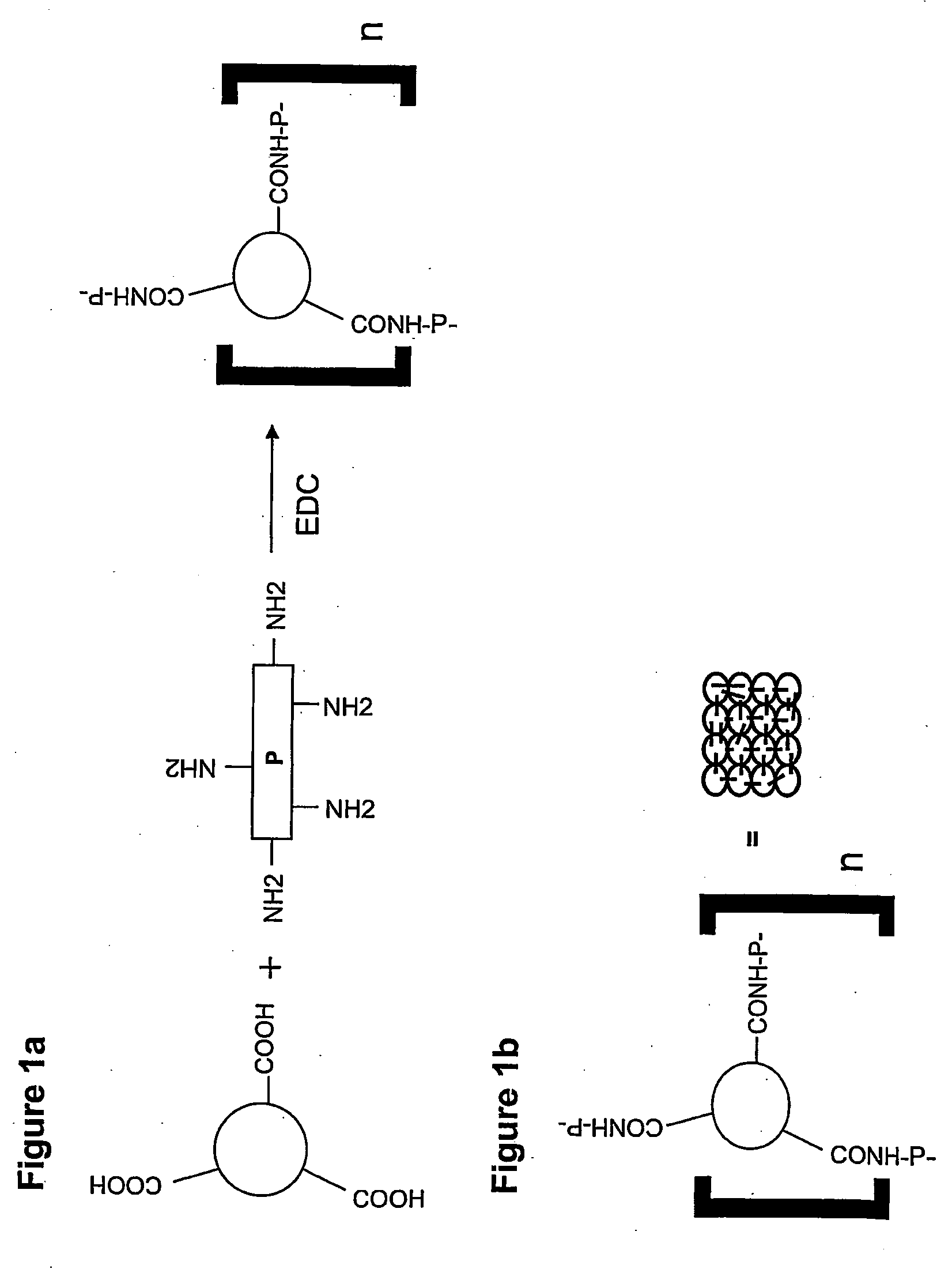
[0129]Hydrogel material was synthesised from bovine serum albumin (BSA) and pNIPAM copolymer particles according to the method of Huang et al [Controlled drug release from hydrogel nanoparticle networks. J Control Release 94:303-311 (2004); US Patent Appln 20030138490], with some modifications. Briefly, 800 μl of pNIPAM-AA in water was lyophilised and re-suspended in 400 μl water. Then, 40 μl of BSA (0.33 mg / μl) and 60 μl of 1-ethyl-3-(3-dimethylaminopropyl)-carbodiimide(EDC) (10% weight / volume) were added to the particles and mixed rapidly with a pipette. The mixture was incubated overnight at room temperature to allow cross-linking to proceed to completion.

example 3

Turbidity of Hydrogel Particle Solution in Relation to Temperature

[0130]The turbidity of pNIPAM-HEA particles suspended in water or 1×PBS was assessed at different temperatures. Turbidity was assessed by measuring changes in the transmission of a 500 nm wavelength of light through the suspension [see method of Gao & Hu (2002) Langmuir 18:1360-1367]. Transmittance was measured using a Versamax (Molecular Dynamic, CA) UV-Vis Spectrometer with temperature control, at temperatures from 20° C. to 45° C. The results of these experiments are presented in FIG. 3.

[0131]The abrupt increase in the turbidity of the suspensions indicates that the LCST has been reached and the hydrogel particles have become hydrophobic, leading to a phase separation.


PUM

PropertyMeasurementUnit
LCSTaaaaaaaaaa
wavelengthsaaaaaaaaaa

Abstract

A composition comprising a hydrogel particle and a fluorophore; wherein said composition produces an enhanced fluorescent signal when excited by an energy source capable of exciting the fluorophore.

Description

FIELD OF THE INVENTION[0001]The present invention relates to compositions and methods for increasing and detecting the fluorescence of fluorescent and non-fluorescent compounds, including biomolecules. The present invention also relates to methods for detecting the presence of compounds, including biomolecules.BACKGROUND ART[0002]In recent years fluorescence has become a dominant technology in fields such as environmental monitoring, biotechnology (eg drug discovery and cellular imaging) and medicine (eg medical testing and imaging). The greatly enhanced ability to detect specific molecules has also led to rapid advancements in diagnostics. For example, fluorescence detection is widely used in medical testing and DNA analysis because of the high degree of sensitivity obtained using fluorescent techniques. Small numbers of molecules can be detected using fluorescence technology.[0003]Most of the knowledge about fluorescence is based on measurements of the spectroscopic properties of ...

Claims


Application Information

Patent Timeline
Patent Type & Authority Applications(United States)
IPC IPC(8): G01N21/64
CPCC12Q1/6818G01N21/6428G01N33/544G01N33/582C12Q2563/179C12Q2563/149C12Q2563/107
Inventor AYI, TECK CHOONTONG, MEI-MEI JILLLEE, VEE SIN PETER
Owner DSO NAT LAB
Why Eureka
Try Eureka