Nanoconfinement- based devices and methods of use thereof

a technology of nanoconfinement and analyte detection, which is applied in the field of devices and methods for rapid analyte detection, can solve the problems of device limitations, analyte detection, and device limitations, and achieve the effects of improving the specificity of binding, improving the accuracy of assays, and fast binding

Inactive Publication Date: 2009-05-28
MASSACHUSETTS INST OF TECH
View PDF7 Cites 54 Cited by
  • Summary
  • Abstract
  • Description
  • Claims
  • Application Information

AI Technical Summary

Benefits of technology

[0026]In another embodiment, the flow velocity (v) is maximized or optimized to allow faster binding and more accurate assays at lower analyte concentrations.
[0027]In another embodiment, the devices/methods/kits of this invention provide for increased specificity of binding between target molecules and cognate binding partner.
[0028]In

Problems solved by technology

The devices are particularly desirable for detection and assay of low-abundance samples, yet such devices suffer a number of limitations to date.
Analyte detection, for example, by immunoassay, in such devices is limited, inter alia, by the existence of surface diffusion layers in such devices, which limits the binding kinetics.
Diffusive transport at that length scale is relatively slow and

Method used


Image

  • Nanoconfinement- based devices and methods of use thereof
  • Nanoconfinement- based devices and methods of use thereof
  • Nanoconfinement- based devices and methods of use thereof

Examples


example 1

Rapid Convection and Sensing Device

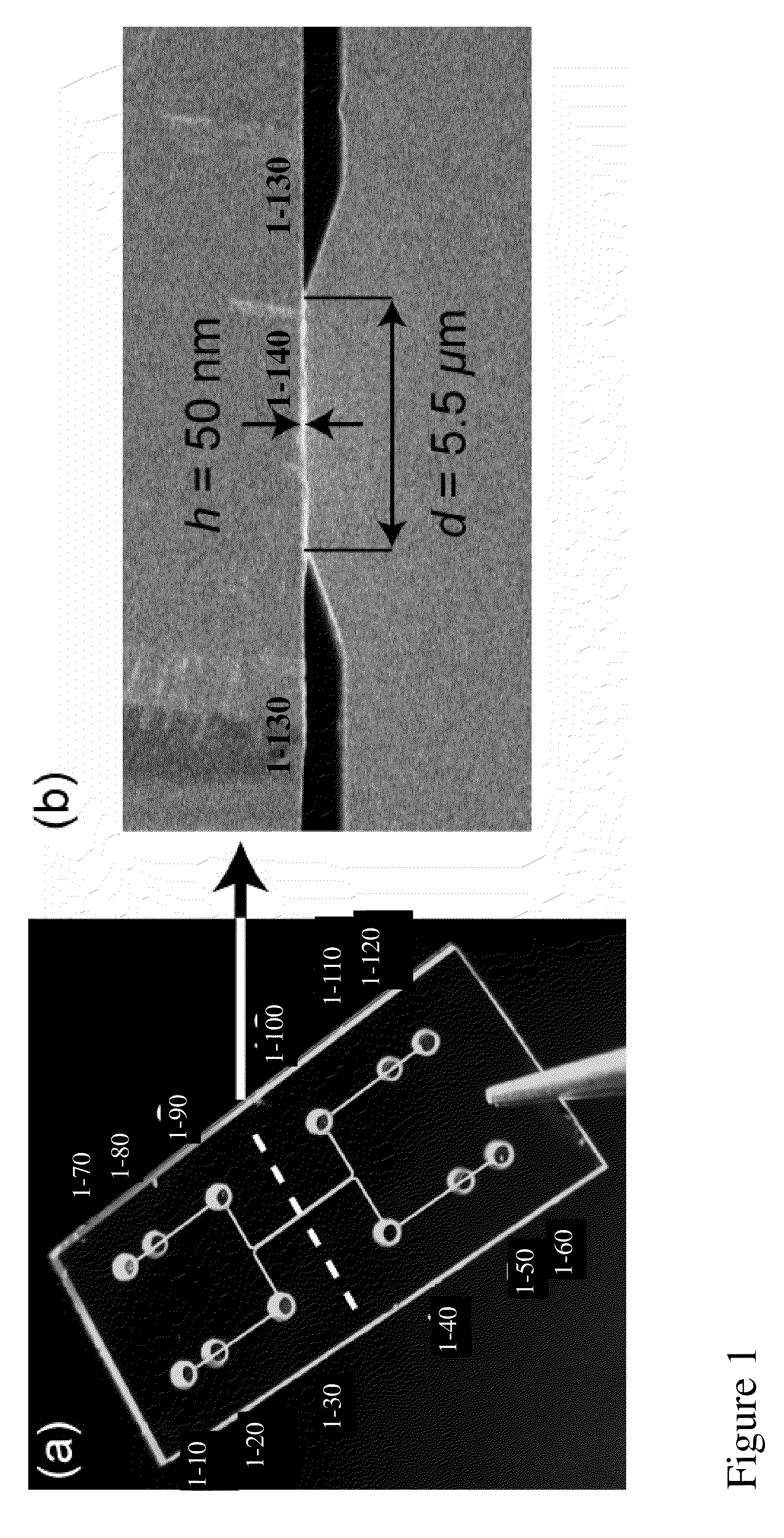
[0230]FIG. 1 describes an embodiment of a device of this invention, depicting a chip comprising nanochannels (1-140), placed proximally to abut microchannels (1-130). Access ports 1-10-1-60 are positioned to the left of the long axis of the microchannels depicted, and holes 1-70-1-120 to the right of the long axis of the microchannels depicted.

[0231]Ports 1-30 / 1-90 and 1-40 / 1-100 provide fluidic access to the microchannel, e.g. for introduction of sample and waste removal of each microchannel, respectively. Electrical contact can be made through the pads in ports 1-10 / 1-70 or 1-60 / 1-120, respectively. To control the pressure in the chip, and / or prevent liquid flow into the electrical contact sites, ports 1-20 / 1-50 and 1-80 / 1-110 may be sealed with nonconductive glue.

[0232]Different chip configurations were fabricated with 1-10, 1-20, 1-50, and 1-100 nanochannels joining the two microchannels. Each nanochannel had the following dimensions: height h=...

example 2

Detection of a Binding Event in Embodied Devices of this Invention

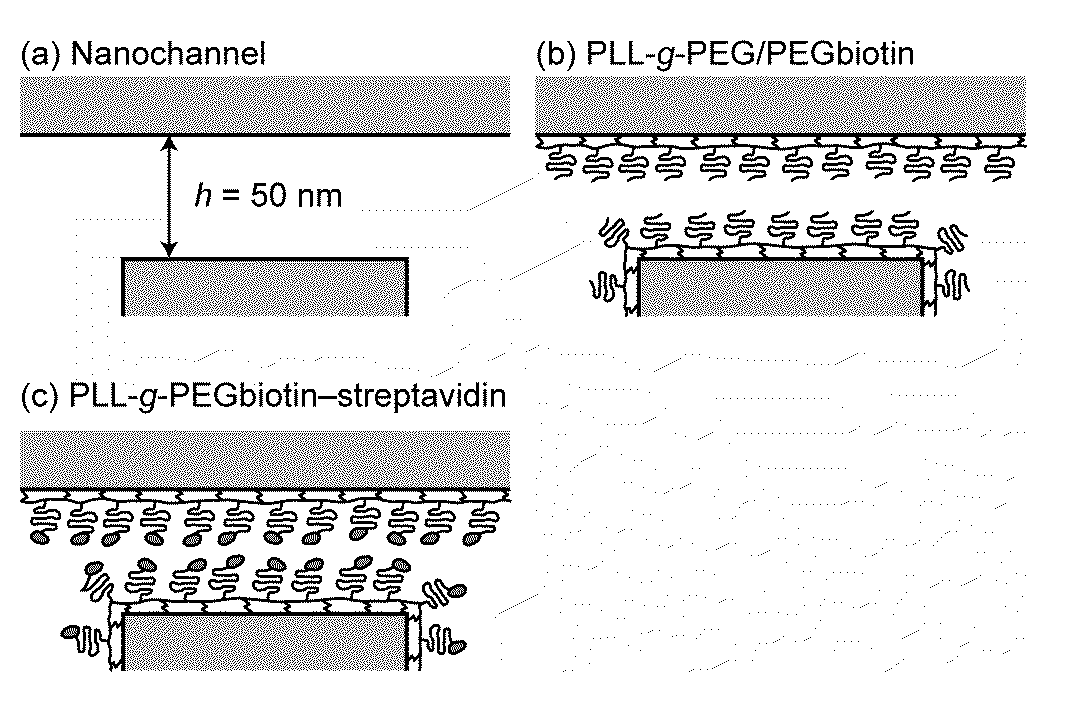
[0235]For electrical detection of immobilized proteins in nanochannels, streptavidin-biotin was chosen as the model receptor-ligand pair. To perform such bindings in nanochannels, surfaces were pre-coated with PLL(20)-g[3.5]-PEG(2) / PEG(3.4)-Biotin (50%) at 0.1 mg / ml (hereinafter referred to as “PLL-g-PEGbiotin”). This polymer is end-functionalized with biotin and therefore reacts selectively with streptavidin. Controls included surfaces pre-coated with 0.1 mg / ml PLL(20)-g[3.5]-PEG(2) (hereinafter referred to as “PLL-g-PEG”) layer, which reduces protein adsorption. The polymers are known to spontaneously adsorb from aqueous solutions to oxide surfaces due to the positively charged poly(L-lysine) group at neutral pH, are protein-resistant due to the poly(ethylene glycol) group forming a comblike structure, and can be end-functionalized to react selectively with a target molecule.

[0236]10 mM HEPES buffer solution having ...

example 3

Concentration-Dependent Effects on Diffusive Binding

[0246]To determine the lowest detectable concentration of biomolecules in a diffusion-limited reaction, the normalized conductance change was investigated as a function of the streptavidin concentration (FIG. 4). In this aspect, the lowest detectable streptavidin concentration in nanochannels is estimated to be 0.4 μM. At lower biomolecule concentrations, detected nanochannel conductance changes were within the repeatability error of ˜3%. The poor detectability at lower streptavidin concentrations can be attributed, in part, to the failure to achieve binding equilibrium.

[0247]The failure of detection of the lowest streptavidin concentrations in FIG. 4 may be attributable to the process of diffusion-limited patterning of nanochannels [see Karnik et al. Karnik, R.; Castelino, K.; Duan, C.; Majumdar, A. Nano Lett. 2006, 6, 1735]. Under diffusion, the coating time tdiff of a nanochannel with a length d is:

tdiff=Pγ0d22DAc(1)

[0248]where ...


PUM

PropertyMeasurementUnit
Lengthaaaaaaaaaa
Lengthaaaaaaaaaa
Lengthaaaaaaaaaa

Abstract

The present invention provides a device/kit and methods of use thereof in rapid detection of target molecule binding to a cognate binding partner. The methods, inter-alia, make use of a device comprising channels or reservoirs, which are linked to nanochannels, whereby upon application of the cognate binding partner to the nanochannel comprising the target molecule under flow, a detectable change in conductance, capacitance or fluorescence or surface potential occurs.

Description

CROSS-REFERENCE TO RELATED APPLICATION[0001]This application claims priority under 35 U.S.C. § 119(e) to U.S. provisional patent application Ser. No. 61 / 001,105, filed Oct. 31, 2007, and is incorporated herein by reference in its entirety.GOVERNMENT SUPPORT[0002]This invention was made in whole or in part with U.S. Government support from the National Institute of Health, Grant Number NIH EB005743. The government has certain rights in the invention.FIELD OF THE INVENTION[0003]This invention provides devices and methods for rapid analyte detection.BACKGROUND OF THE INVENTION[0004]Lab-on-chip devices and applications represent a cost-effective means for rapid throughput assay and detection of materials of interest. The devices are particularly desirable for detection and assay of low-abundance samples, yet such devices suffer a number of limitations to date. Analyte detection, for example, by immunoassay, in such devices is limited, inter alia, by the existence of surface diffusion la...

Claims


Application Information

Patent Timeline
IPC IPC(8): C12Q1/68B01J19/00C12M1/00G01N21/64G01N27/00C12Q1/02G01N33/00G01N33/53
CPCB01L3/502761B01L2200/0663B01L2300/0896B01L2400/0415B01L2400/0418B01L2400/0421Y10T436/143333B82Y5/00B82Y15/00B82Y30/00G01N21/6428G01N33/5302G01N33/558B01L2400/0487
Inventor HAN, JONGYOONSCHOCH, RETO B.CHEOW, LIH FENG
Owner MASSACHUSETTS INST OF TECH
Why Eureka
Try Eureka