
Systems and methods for carbon capture and sequestration and compositions derived therefrom

a carbon capture and sequestration and carbon dioxide technology, applied in the field of systems and methods for carbon capture and sequestration and compositions derived therefrom, can solve the problems of generating carbon dioxide, among other toxic and/or greenhouse gases, at very significant levels, and sub>2 /sub>(pcc) from flue gas remains a challeng

Active Publication Date: 2009-06-04
RUTGERS THE STATE UNIV
View PDF53 Cites 157 Cited by
  • Summary
  • Abstract
  • Description
  • Claims
  • Application Information

AI Technical Summary

Benefits of technology

[0008]Another embodiment provides a ceramic produced by a carbon capturing, carbon sequestering process, or a combination thereof, which process comprises allowing at least one component of a porous matrix to undergo a reaction with at least a first reactant carried by a infiltrating medium to provide at least a first product, during which reaction a remainder of the porous matrix acts as a scaffold for facilitating the formation of the first product from the reaction mixture, thereby producing a ceramic.
[0009]In another embodiment, a method of making a ceramic is provided, the method comprising: (i) providing a porous matrix having interstitial spaces and comprising at least a first reactant; (ii) contacting the porous matrix with an infiltrating medium that carries at least a second reactant, which comprises a greenhouse gas; (iii) allowing the infiltrating medium to infiltrate at least a portion of the interior spaces of the porous matrix under conditions that promote a reaction between the at least first reactant and the at least second reactant to provide at least a first product; and (iv) allowing the at least first product to form and fill at least a portion of the interstitial spaces of the porous matrix, thereby producing a ceramic, wherein the method consumes and does not release significant amounts of greenhouse gas.

Problems solved by technology

Materials in the construction industry, such as steel and cement, generate carbon dioxide, among other toxic and / or greenhouse gases, at very significant levels.
Third, electrical energy needed for driving process equipment such as the rotary calciner and milling equipment.
Even processes such as these are energy intensive.
Furthermore, the post-combustion capture of CO2 (PCC) from flue-gas remains a challenge.
For example, problems such as backpressures can limit the output of a power plant.
Further, the capture process is frequently limited by the conditions of the combustion, which are determined by the chemistry of the fuel being burned as well as the selected combustion conditions.
For example, amine-based capture methods require low temperatures for high CO2 capture efficiency, which introduces energy costs for cooling the flue gas and a CO2 footprint associated with the energy.

Method used


Image

  • Systems and methods for carbon capture and sequestration and compositions derived therefrom
  • Systems and methods for carbon capture and sequestration and compositions derived therefrom
  • Systems and methods for carbon capture and sequestration and compositions derived therefrom

Examples


working examples

NON-LIMITING WORKING EXAMPLES

Example 1. Calcium Carbonate From Calcium Hydroxide And Potassium Carbonate

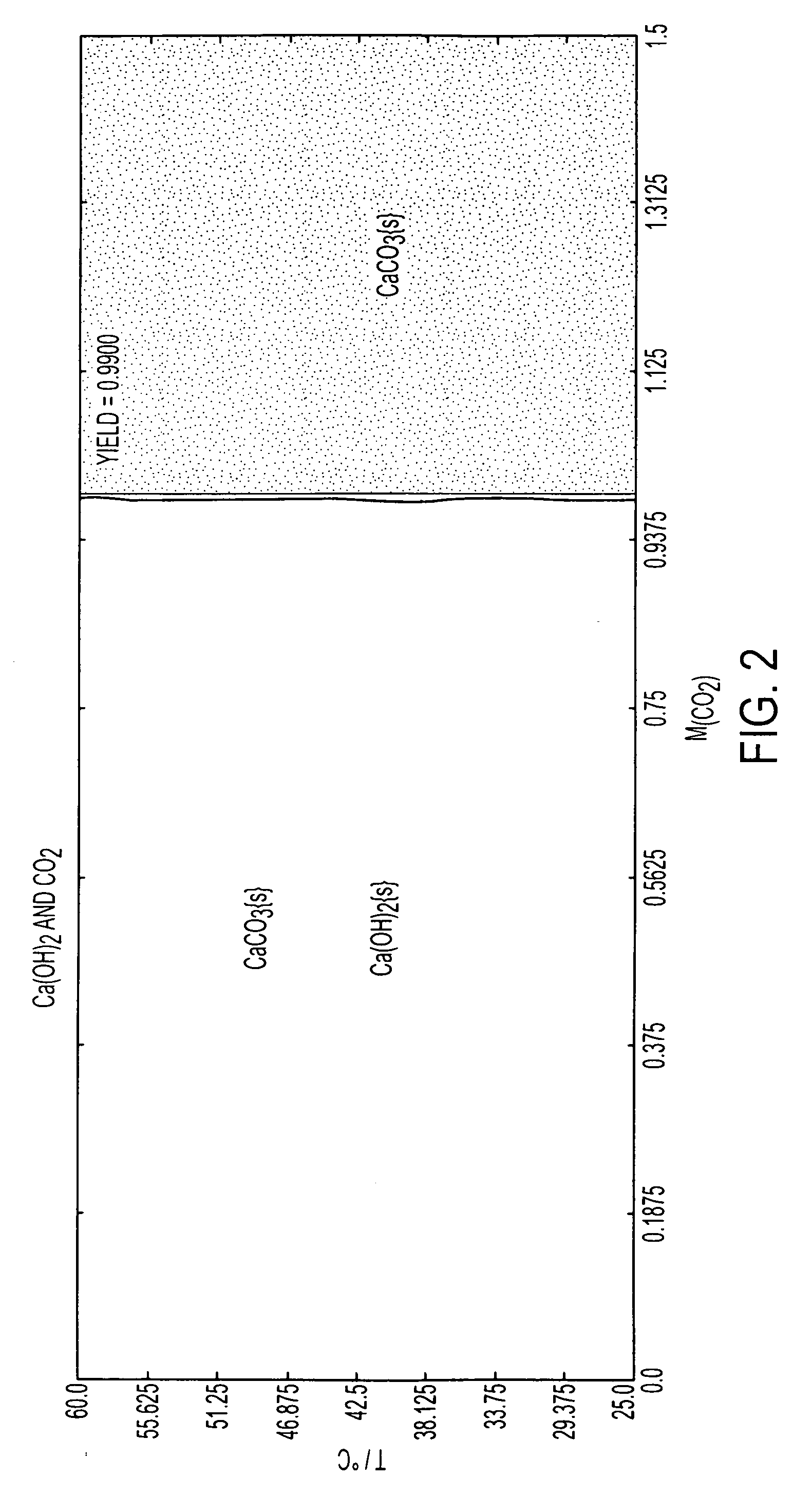
[0104]Calcium oxide powder, ˜5 g, was reacted with ˜100 ml de-ionized water to form Ca(OH)2 in Teflon jar at room temperature. The calcium hydroxide and water mixture was cooled down to room temperature. It was then shaken and poured into colloidal press until the reservoir was filled roughly around 75%. A load of 7000 pounds was applied on the colloidal press slowly. A Teflon™ jar was filled with 200 ml of de-ionized water and 30 g of K2CO3 was dissolved in it. Wet Ca(OH)2 pellet was placed on a Teflon tray and placed in the Teflon jar. The cap of the jar was closed and kept at room temperature for 4 days. The pellet was then taken out and rinsed with de-ionized water. The reaction product was subjected to x-ray diffraction and was found to comprise mainly CaCO3 with a small amount of Ca(OH)2. The sample maintained its shape and had sufficient mechanical strength to resist fractu...

example 2

xalate Monohydrate From Calcium Hydroxide And Oxalic Acid

[0105]Calcium oxide powder, 5 g, was reacted with 100 ml de-ionized water to form Ca(OH)2 in a Teflon™ jar at room temperature. The calcium hydroxide and water mixture was cooled down to room temperature. It was then shaken and poured into a 1″ diameter colloidal (filter) press until the reservoir was filled roughly around 75%. A load of 7000 pounds was applied on the colloidal press slowly. The Teflon jar was filled with 200 ml of de-ionized water and 30 g of H2C2O4 were mixed. The wet Ca(OH)2 pellet was placed on a Teflon™ tray and placed in the Teflon™ jar. The cap of the jar was closed and kept at room temperature for 4 days. The pellet was then taken out and rinsed with de-ionized water. X-ray diffraction revealed the presence of both CaC2O4·H2O and Ca(OH)2. The sample maintained its shape and size as pressed and did not change dimensions after hydrothermal liquid phase sintering The material is mechanically stable. A mor...


PUM

PropertyMeasurementUnit
Temperatureaaaaaaaaaa

Abstract

A method of sequestering a greenhouse gas is described, which comprises: (i) providing a solution carrying a first reagent that is capable of reacting with a greenhouse gas; (ii) contacting the solution with a greenhouse gas under conditions that promote a reaction between the at least first reagent and the greenhouse gas to produce at least a first reactant; (iii) providing a porous matrix having interstitial spaces and comprising at least a second reactant; (iv) allowing a solution carrying the at least first reactant to infiltrate at least a substantial portion of the interstitial spaces of the porous matrix under conditions that promote a reaction between the at least first reactant and the at least second reactant to provide at least a first product; and (v) allowing the at least first product to form and fill at least a portion of the interior spaces of the porous matrix, thereby sequestering a greenhouse gas.

Description

RELATED APPLICATION[0001]This application claims priority to US provisional patent application Ser. No. 60 / 988,122 filed Nov. 15, 2007, which is herein incorporated by reference in its entirety.BACKGROUND[0002]Global warming has received increasing attention owing to greater acceptance of proposed theories, which include the increasing release of carbon dioxide, a green house gas. Global releases of carbon dioxide was 49 billion tons in 2004, which was an 80% increase over 1970 levels. The emissions of carbon dioxide in 2005 in the USA alone was 6.0 billion metric tons. Materials in the construction industry, such as steel and cement, generate carbon dioxide, among other toxic and / or greenhouse gases, at very significant levels. In 2002, the EPA estimates that cement production accounts for 5 wt % of the world production of carbon dioxide and ties the steel industry for being the most significant industrial contributors of carbon dioxide. Carbon dioxide release is attributed to thre...

Claims


Application Information

Patent Timeline
IPC IPC(8): B01D53/46C04B32/00B01D53/48B01D53/54C04B35/00C01B32/50C01B32/60
CPCB01D53/62B01D53/73B01D2251/404B01D2257/504C04B40/0268C01F11/18Y02C10/04C04B40/0236C01D7/07Y02P20/151Y10T428/249921Y02C20/40Y02P40/18B01D53/00
Inventor RIMAN, RICHARD E.ATAKAN, VAHIT
Owner RUTGERS THE STATE UNIV
Learn More