
Temperature sensor circuit

a temperature sensor and circuit technology, applied in the field of temperature sensor circuits, can solve the problems of inability to implement circuits, inability to improve the accuracy of sensing temperature, and difficulty in improving accuracy, so as to achieve excellent temperature linearity and ease of amplifying

Inactive Publication Date: 2009-06-11
NEC ELECTRONICS CORP
View PDF4 Cites 18 Cited by
  • Summary
  • Abstract
  • Description
  • Claims
  • Application Information

AI Technical Summary

Benefits of technology

[0012]Accordingly, it is an object of the present invention to provide a temperature sensor circuit which may be operated at a voltage from and inclusive of a low voltage, may exhibit good temperature linearity and which may be formed with advantage on a semiconductor integrated circuit.
[0020]According to the present invention, a sensing signal may be amplified with ease because a desired voltage may be obtained as a differential voltage.

Problems solved by technology

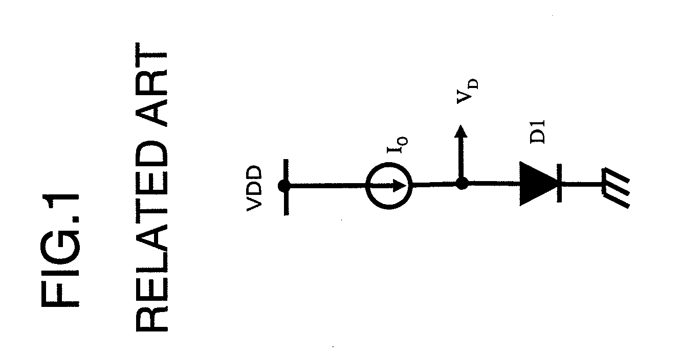
With the above-described temperature sensor circuit, in which the diode forward voltage is exploited, it becomes difficult to improve the accuracy because of temperature non-linearity.
If this voltage is amplified, the power supply voltage increases to a higher value to render it impossible to implement the circuit.
The first problem is that the accuracy in sensing temperature cannot be improved because of temperature non-linearity in the diode forward voltage.
The second problem is that the terminal voltage of the diode cannot be amplified because the diode forward voltage is as large as approximately 0.6V so that limitation is imposed from the power supply voltage.

Method used


Image

  • Temperature sensor circuit
  • Temperature sensor circuit
  • Temperature sensor circuit

Examples


Embodiment Construction

[0027]Exemplary embodiments of the present invention are now described with reference to the drawings.

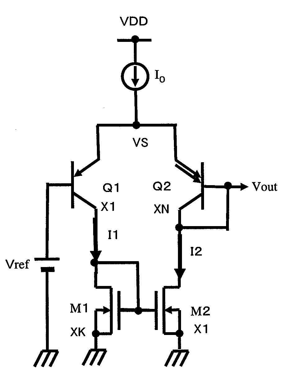
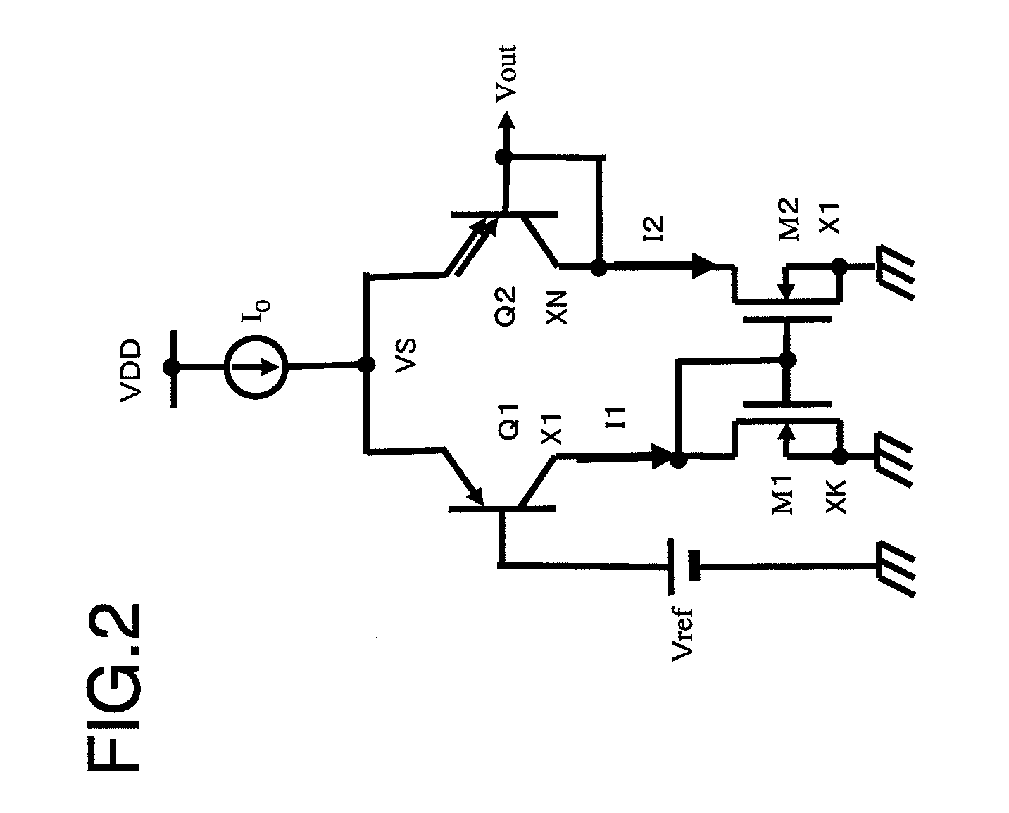
[0028]FIG. 2 depicts a circuit configuration of an exemplary embodiment of a temperature sensor circuit. This configuration corresponds to claim 1. Referring to FIG. 2, the circuit includes a bipolar differential pair transistors (pnp bipolar transistors) (Q1, Q2), having coupled emitters connected to one end of a constant current source I0, the other end of which is connected to a power supply VDD and N-channel MOS transistors (M1, M2) which are connected to the collectors of the differential pair transistors (Q1, Q2) to constitute a current mirror. A reference voltage (constant voltage) Vref is applied to the base of the bipolar transistor Q1. The collector and the base of the bipolar transistor Q2 are connected together and an output voltage Vout is produced at the connection node of the collector and base of the bipolar transistor Q2.

[0029]The bipolar transistors Q1 and Q2 are n...


PUM


Abstract

Disclosed is a temperature sensor circuit including a bipolar differential pair driven by a constant current and having an emitter area ratio of 1:N (N>1) and two MOS transistors having the transistor size ratio of K:1 (K>1) connected as an active load to the bipolar differential pair. A reference voltage is applied to one of the transistors of the bipolar differential pair. The other transistor has a base and a collector connected together. A desired voltage is output between the bases of the two transistors of the bipolar differential pair. A plural number of the temperature sensor circuits may be connected in cascade (FIG. 3).

Description

REFERENCE TO RELATED APPLICATION[0001]This application is based upon and claims the benefit of the priority of Japanese patent application No. 2007-319764, filed on Dec. 11, 2007, the disclosure of which is incorporated herein in its entirety by reference thereto.TECHNICAL FIELD[0002]This invention relates to a temperature sensor circuit. More particularly, it relates to a temperature sensor circuit which may be operated at a low voltage, may exhibit good temperature linearity, and which may be formed with advantage on a semiconductor integrated circuit.BACKGROUND[0003]Among known temperature sensor circuits of this type, there is such a circuit that makes use of a forward voltage of a diode, as shown in FIG. 1. The forward voltage of the diode has a negative temperature characteristic, in which the temperature coefficient is −2.2 mV / ° C. or −1.9 mV / ° C.[0004]However, the diode forward voltage suffers marked temperature non-linearity and, when it is used for a temperature sensor, an...

Claims


Application Information

Patent Timeline
IPC IPC(8): H01L35/00
CPCG01K1/026G05F3/245G01K7/01
Inventor KIMURA, KATSUJI
Owner NEC ELECTRONICS CORP
Learn More