Mold Forming and Molding Method

Inactive Publication Date: 2009-06-25
KYOCERA CORP
View PDF3 Cites 44 Cited by
  • Summary
  • Abstract
  • Description
  • Claims
  • Application Information

AI Technical Summary

Benefits of technology

[0010]A mold forming and molding technology operable to produce a silicon ingot suitable for obtaining a solar cell substrate is disclosed. A slurry is prepared comprising particles with surface oxide layers operable to bond the particles to each other.

Problems solved by technology

When a silicon melt fused with the mold in this way is solidified and cooled in the mold, the difference in thermal shrinkage between the material of the mold base and silicon causes flaws in the silicon ingot.
Examples of flaws are cracking of the silicon ingot, incapability of releasing the silicon ingot from the mold (i.e., the molded silicon ingot gets stuck in the mold), and chipping of the silicon ingot occurring during releasing of the silicon ingot from the mold.
This can increase the proportion of rejected silicon substrates, and can cause breakage of a wire of a wire saw during slicing of a silicon ingot with the wire saw.
When bulky particles or clusters of particles such as cohered particles or fused particles are present in a releasi

Method used


Image

  • Mold Forming and Molding Method
  • Mold Forming and Molding Method
  • Mold Forming and Molding Method

Examples


modified embodiment

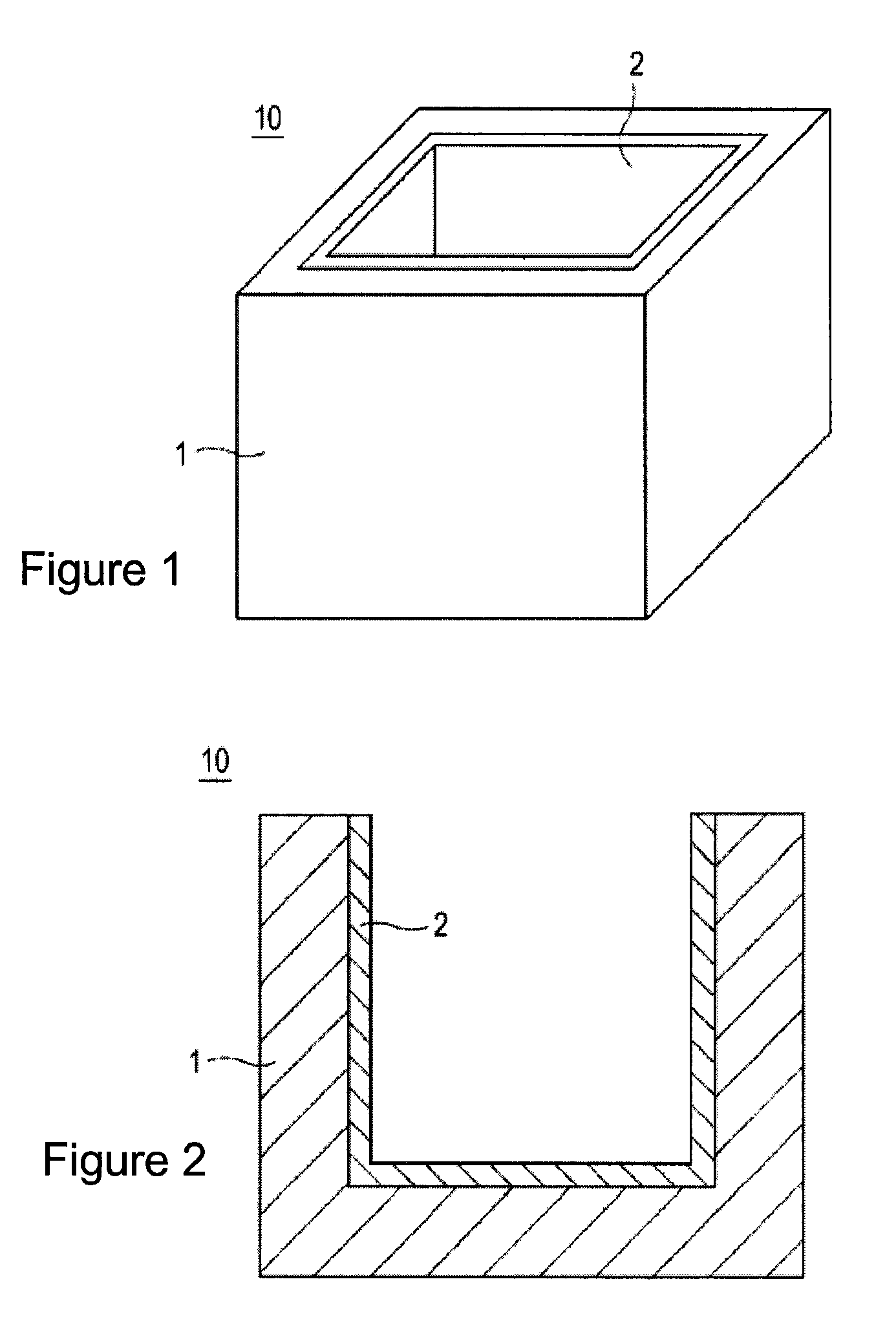
[0109]FIGS. 6A-6C are illustrations of schematic views of mold 10 according to one or more embodiments of the disclosure. The mold 10 may comprise the mold base 1, the releasing layer 2, a separating layer 3, and contain a silicon melt 4. FIGS. 6A-6C may share the same parameters, definition and functionality as FIGS. 1-2. Therefore, these definitions and the functionalities are not redundantly explained herein.

[0110]FIG. 6A is a schematic section view illustration of a mold configuration according to an embodiment of the disclosure. The mold base 1 may be composed of a carbon fiber reinforced material. The separating layer 3 is located between the mold base 1 and the releasing layer 2. Notably, the separating layer 3 is not formed in an upper portion of a mold side wall 10a where a silicon melt does not reach (a portion located at a higher level than the surface of a silicon melt). Although the separating layer 3 is not formed in the portion higher than the surface of the silicon m...

example 1

[0118]Three slurries were prepared under different disintegration treatment conditions and releasing layers were formed with the respective slurries to provide three molds.

[0119]A high purity silicon nitride powder was prepared that was obtained by an imide decomposition method and had an average particle size of about 0.5 μm. The powder was subjected to a surface oxidation treatment by heating the powder at about 1000° C. for about 5 hours with an electric furnace. In an example, SN-E10 manufactured by Ube Industries, Ltd is used as the high purity silicon nitride powder,

[0120]The resultant silicon nitride powder and an about 8% aqueous solution of polyvinyl alcohol were mixed with a blade mixer to prepare a slurry. The mixing ratio of the aqueous solution of polyvinyl alcohol to the silicon nitride powder by weight was about 0.48.

[0121]Specifically, the slurry was prepared by the first agitation step in which the aqueous solution of polyvinyl alcohol in 9 / 10 of the total amount of...

example 2

[0139]For the second example, three releasing agent slurries E, F, and G were prepared by respectively adding silicon dioxide powder in different weight ratios to the releasing agent slurry A prepared in the same manner as in example 1. For the releasing agent slurry E, the ratio of silicon nitride powder to silicon dioxide powder was 8 to 2. For the releasing agent slurry F, the ratio of silicon nitride powder to silicon dioxide powder was 6 to 4. For the releasing agent slurry G, the ratio of silicon nitride powder to silicon dioxide powder was 5 to 5.

[0140]Silicon ingots were produced with these three releasing agent slurries E, F, and G as in example 1. These silicon ingots were sliced into wafers. These wafers were processed into solar cell elements. In the production of the silicon ingots, the wafers, and the solar cell elements, the occurrence of adhesion between the mold bases and the releasing layers was detected, and the proportion of the wafers rejected because of foreign...


PUM

PropertyMeasurementUnit
Fractionaaaaaaaaaa
Percent by massaaaaaaaaaa
Viscosityaaaaaaaaaa

Abstract

A mold forming and molding technology operable to produce a silicon ingot suitable for obtaining a solar cell substrate is disclosed. A slurry is prepared comprising particles with surface oxide layers operable to bond the particles to each other. An external force is applied to the slurry to eliminate cohesion of the particles to form a de-cohesive slurry, and an inner surface of a mold base is coated with the de-cohesive slurry to form a releasing layer that reduces defects in the silicon ingot.

Description

CROSS-REFERENCE TO RELATED APPLICATION[0001]This application is a continuation in part based on PCT application PCT / JP2007 / 066892 filed on Aug. 30, 2007, which claims the benefit of Japanese national application JP2006-233661 filed on Aug. 30, 2006, the entirety of both of which are incorporated by reference herein.FIELD OF INVENTION[0002]Embodiments of the present disclosure relate generally to manufacturing of a solar cell element, and more particularly relate to a mold used for manufacturing a silicon ingot for providing a substrate for a solar cell element.BACKGROUND OF THE INVENTION[0003]Polycrystalline silicon substrates are a type of a semiconductor substrate that have been used for forming solar cell elements. Polycrystalline silicon substrates are obtained by slicing a silicon ingot. The silicon ingot may be produced by, for example, a method of feeding melted silicon into a mold and solidifying the silicon. The silicon ingot may also be produced by a method of melting a si...

Claims


Application Information

Patent Timeline
IPC IPC(8): B28B7/38
CPCC01B33/02C30B11/002Y02E10/546H01L31/182H01L31/04Y02P70/50
Inventor TSUCHIDA, MASAHIROGOTO, SHIGERUOKUSHIMA, KENTAROYAMATANI, MUNEYOSHI
Owner KYOCERA CORP
Why Eureka
Try Eureka