

Fuel injection control apparatus for internal combustion engine
- Summary
- Abstract
- Description
- Claims
- Application Information
AI Technical Summary
Benefits of technology
Problems solved by technology
Method used
Image

Examples
first embodiment
[0037]The configuration and operation of a fuel injection control apparatus for an internal combustion engine according to the present invention will be described hereunder using FIGS. 1 to 7.
[0038]First, an internal combustion engine system configuration with the fuel injection control apparatus for an internal combustion engine according to the first embodiment of the present invention will be described using FIG. 1.
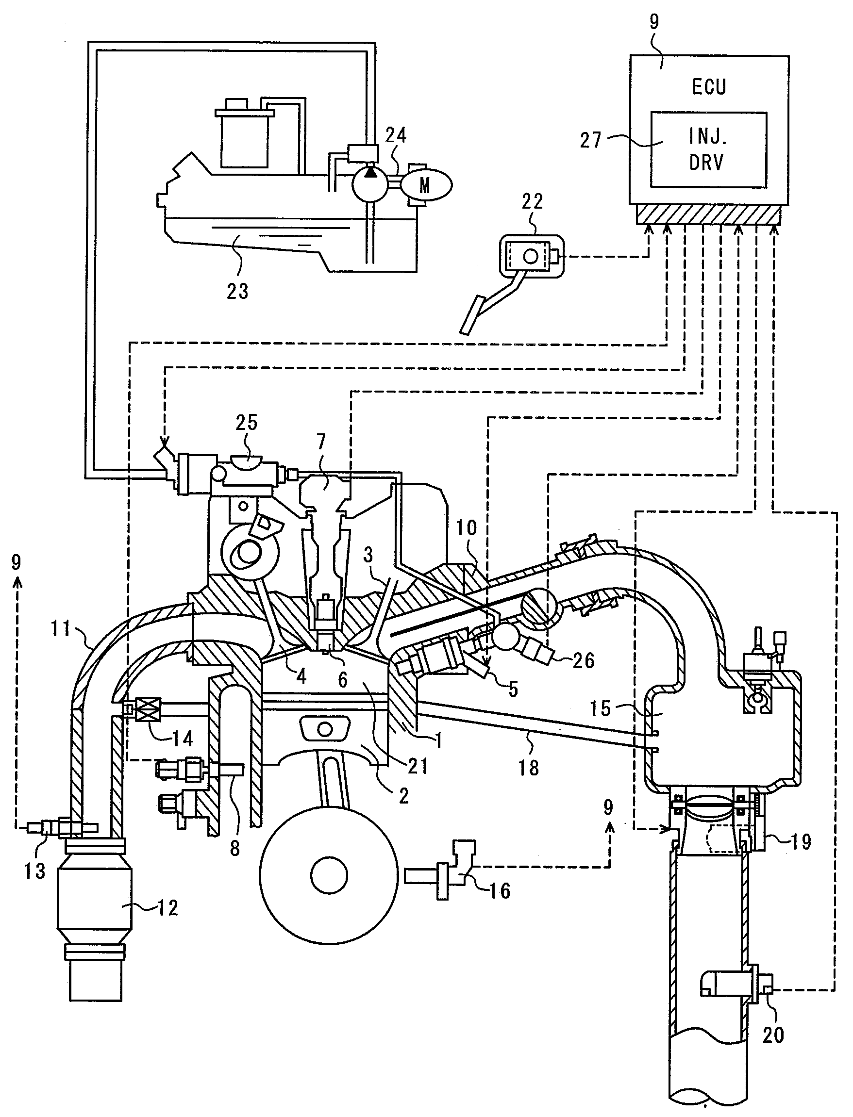
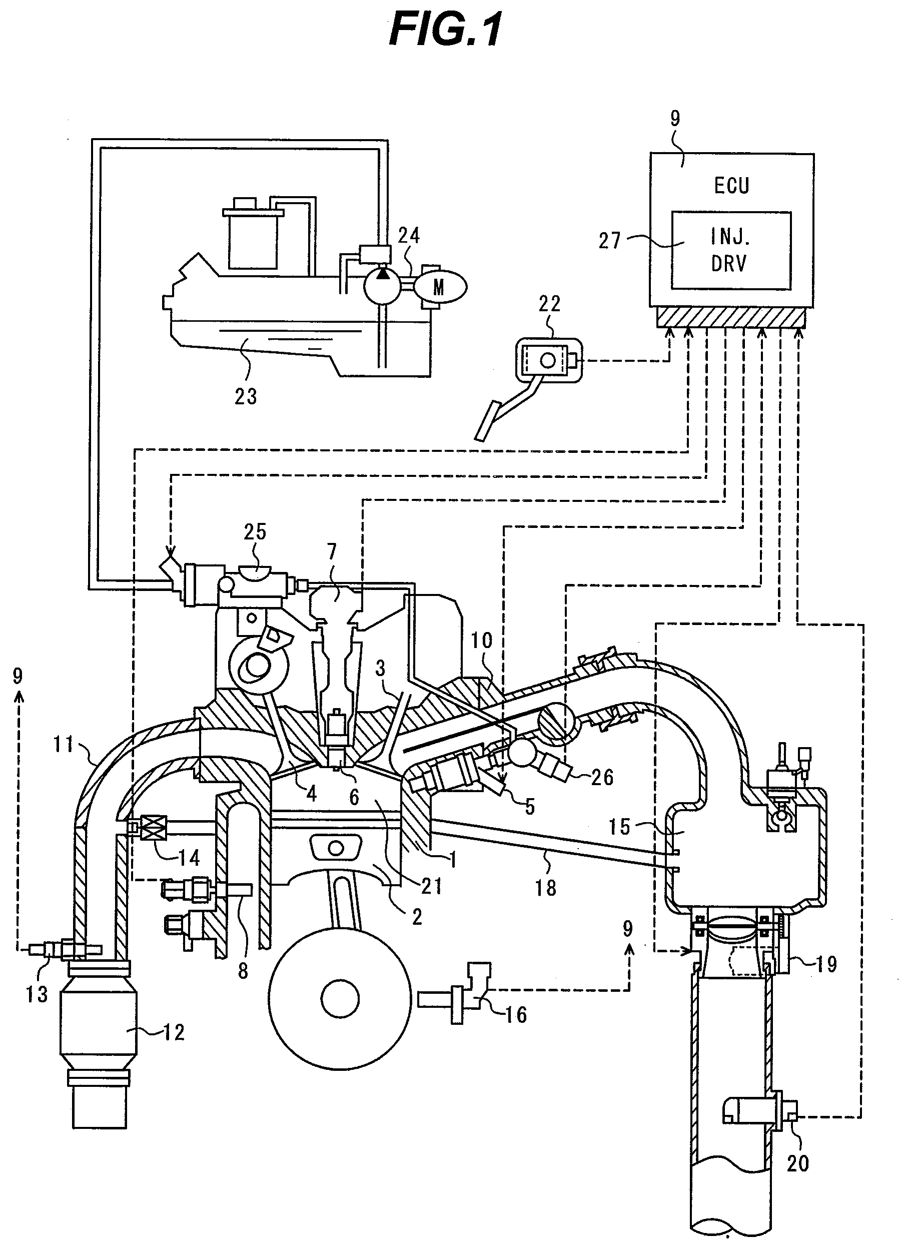
[0039]FIG. 1 is a block diagram of the internal combustion engine system with the internal combustion engine fuel injection control apparatus according to the first embodiment of the present invention.
[0040]The engine 1 includes a piston 2, an air suction valve 3, and an exhaust valve 4. Suction air is passed through an air flowmeter (AFM) 20, then enters a throttle valve 19, and supplied from a collector 15 that is a branch section, through an air suction pipe 10 and the suction valve 3 to a combustion chamber 21 of the engine 1. Fuel is supplied from a fuel tank 23 t...
second embodiment
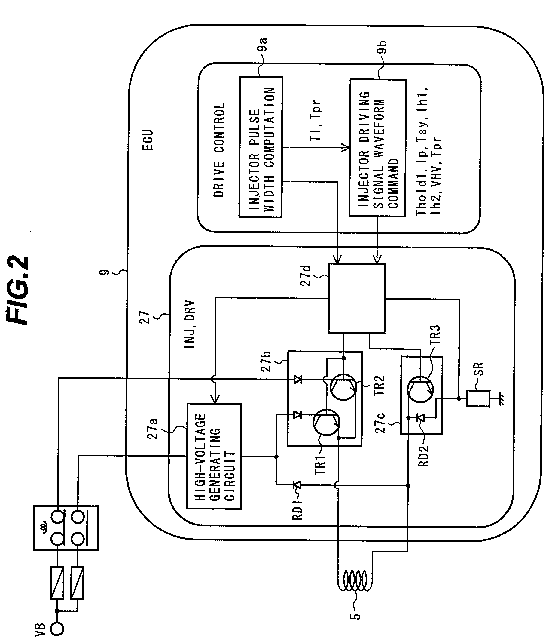
[0114]The configuration and operation of a fuel injection control apparatus for an internal combustion engine according to the present invention will be described hereunder using FIG. 8. The description assumes that an internal combustion engine system configuration with the internal combustion engine fuel injection control apparatus according to the present embodiment is essentially the same as the system configuration shown in FIG. 1. The description also assumes that the configuration of the internal combustion engine fuel injection control apparatus according to the present embodiment is essentially the same as the system configuration shown in FIG. 2. In addition, the description assumes that the operation of the internal combustion engine fuel injection control apparatus, achieved in the present embodiment when the fuel injection pulse width is large, is essentially the same as the system configuration shown in FIG. 3. Furthermore, the description assumes that control by the i...
third embodiment
[0131]The configuration and operation of a fuel injection control apparatus for an internal combustion engine according to the present invention will be described hereunder using FIG. 9. The description assumes that an internal combustion engine system configuration with the internal combustion engine fuel injection control apparatus according to the present embodiment is essentially the same as the system configuration shown in FIG. 1. The description also assumes that the configuration of the internal combustion engine fuel injection control apparatus according to the present embodiment is essentially the same as the system configuration shown in FIG. 2. In addition, the description assumes that the operation of the internal combustion engine fuel injection control apparatus, achieved in the present embodiment when the fuel injection pulse width is large, is essentially the same as the system configuration shown in FIG. 3. Furthermore, the description assumes that control by the i...
PUM
 Abstract
Description
Claims
Application Information