System and process for ultrasonic characterization of deformed structures

a technology of ultrasonic characterization and process, applied in the field of ultrasonic assessment methods and systems, can solve the problems of delayed failure, difficult measurement required to make these assessments, and failures that may occur immediately, so as to achieve effective deployment, reduce the burden of measurement, and reduce the cost

Active Publication Date: 2009-08-06
BATTELLE MEMORIAL INST
View PDF12 Cites 44 Cited by
  • Summary
  • Abstract
  • Description
  • Claims
  • Application Information

AI Technical Summary

Benefits of technology

[0010]Once these calculated parameters have been plotted, a curve or line is fitted to the data points, for each set of values. Comparing these curves of plotted data then provides a visual array that demonstrates how test values move away from baseline data. Location and magnitude of these variations provide information that demonstrates the location and severity of the damage to the structure being examined. Comparative studies based on a direct measurement of material properties rather than thickness have shown that the results obtained using this method correlate well with more burdensome and costly methods while doing so in a faster more efficient manner. Therefore, enabling devices that employ these methods can be effectively deployed. Since this method has increased efficiency particularly as compared to other methods, smaller devices that require less energy can be utilized to accomplish the calculations required by this method.
[0011]This arrangement provides a variety of advantages over the devices and methods that are taught in the prior art. By focusing scans on preselected portions of the pipe, the entire inner portion of the pipe need not be scanned and surveyed. This allows for increased speed in moving the device along the pipe and also limits the number of data points that are collected thus allowing for more efficient and quick computational results, and requires less reduced electrical power than other methods or devices. Devices that employ the present method may be used on pipe PIGs or saddle PIGs that obtain measurements of the pipe from either the inside or the outside of the pipe, respectively. In addition the present invention may be used with pipes that are full or empty and which have mixed gas and liquid phases and materials within these pipes.

Problems solved by technology

Immediate failure may occur, for example, when construction equipment punctures the pipeline and produces a leak at the time of damage.
However, mechanical deformation and damage more frequently provide an initiation site for crack formation and delayed failure.
Unreported deformation, for example, can result in delayed failure due to either slow crack growth through the thickness or hydrogen-stress cracking of the cold worked and strain-aged steel.
Often these delayed failures are caused by fatigue cracks which grow due to cyclic stressing at deformed and damaged locations.
Measurements required to make these assessments can be particularly difficult in situations where structures that need to be analyzed are large in size and / or are difficult to remove or access.
Current methods for determining the degree of deformation and / or damage (including, e.g., strain) in various regions of a closed structure such as a pipeline can be complicated and expensive and in some cases impossible due to a variety of factors including, but not limited to, microstructure texture variations in the materials that make up the structures and the difficulty in separating these effects from damage.

Method used


Image

  • System and process for ultrasonic characterization of deformed structures
  • System and process for ultrasonic characterization of deformed structures
  • System and process for ultrasonic characterization of deformed structures

Examples


example 1

Nondestructive Examination (NDE) Measurements of a Bulged Pipeline

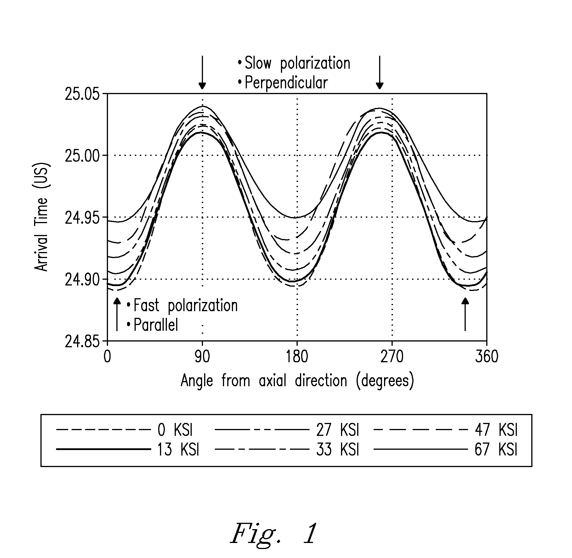
[0057]Scanning measurements were collected for a 20″ diameter natural gas pipeline removed from service after a significant bulge was found. Scans were performed at several positions around the circumference. In one test, as the EMAT scanned the pipeline, time (i.e., time-of-flight) required for shear waves to traverse the thickness of the pipeline several times was determined every 0.1 inches along the axis of the pipeline. Spot measurements were also performed using time of flight of the shear waves to measure scanning effects when determining shear wave birefringence.

example 2

NDE Measurements and Assessment of Damaged Pipelines Along a Fault

[0058]Ultrasonic measurements of the strain (due to bending) were collected on bent pipelines replacing a section of a natural gas pipeline which crossed an earthquake fault in the San Francisco Bay Area (California, USA). Data collected on straight and bent pipelines provided useful data for determining the precision, accuracy, and minimum detectable strain levels. Critical baseline measurements were obtained on bent pipelines prior to installation of the replacement pipelines, thus allowing for future assessment of the integrity of the pipeline should subsequent earth movements be detected along the fault. Thirteen 40 foot sections of X60 / X65 pipeline were available for testing at the fault crossing work site. Pipelines were nominally 40 feet long, 36″ in diameter and ½″ thick. Ultrasonic measurements were collected on 5 straight pipelines. Pipeline ends were labeled “A” and “B”. Scans were started from end “B” and ...

example 3

NDE Measurements of Dented Pipelines

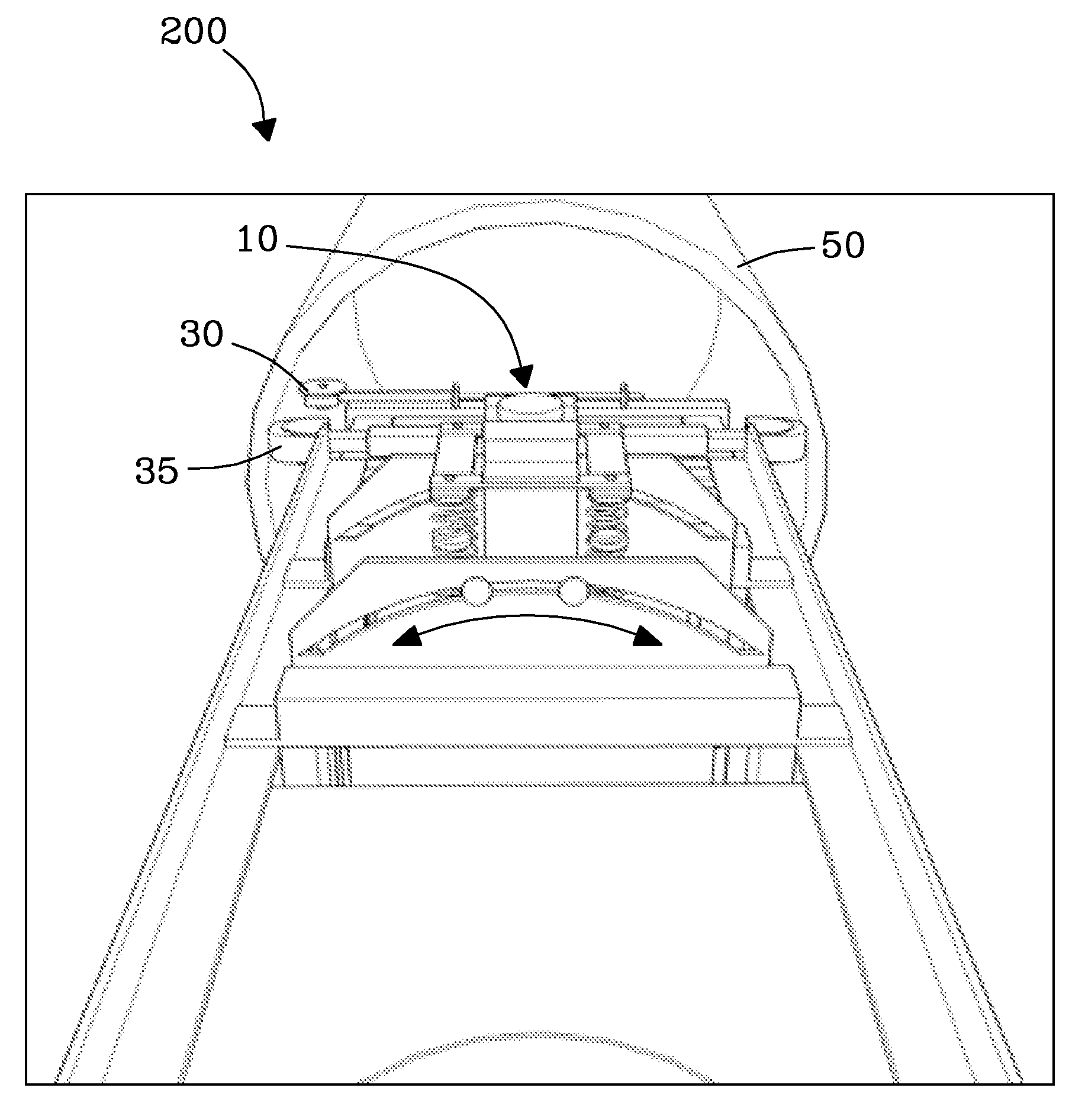
[0059]Dented pipelines were scanned under remote control along the axis of the pipeline from the interior. Pipeline was scanned from the interior along the axis utilizing the non-contact EMAT sensor in the motorized cart configuration. Preferred speeds were greater than 2″ per second, but are not limited thereto. The EMAT generated a wave which traveled through the thickness of the pipeline every 0.2″ along the axis of the pipeline as the sensor was moved continuously along the pipeline. Data were collected every 0.2″ along the axis length, but again are not limited thereto.


PUM

PropertyMeasurementUnit
lengthaaaaaaaaaa
anglesaaaaaaaaaa
speedaaaaaaaaaa

Abstract

Generally speaking, the method of the present invention is performed by making various ultrasonic scans at preselected orientations along the length of a material being tested. Data from the scans are then plotted together with various calculated parameters that are calculated from this data. Lines or curves are then fitted to the respective plotted points. Review of these plotted curves allows the location and severity of defects within these sections to be determined and quantified. With this information various other decisions related to how, when or whether repair or replacement of a particular portion of a structure can be made.

Description

[0001]This invention was made with Government support under Contract DE-AC05-76RL01830 awarded by the U.S. Department of Energy. The Government has certain rights in the invention.FIELD OF THE INVENTION[0002]The invention relates generally to ultrasonic assessment methods and systems. More particularly, the invention is a system and process for ultrasonic characterization of deformed structures such as deformed containment vessels, pipelines, bridges, rail systems, vehicles, and the like.BACKGROUND OF THE INVENTION[0003]Assessing and maintaining integrity of aging structures are of primary importance. Specifically, there is a need to detect and characterize degradation to infrastructure to allow for proactive measures to be taken to minimize potential losses of life and damage to property and natural resources. Examples of the various needs for information vary by particular industry. However, the underlying theme in nearly all questions is answering this fundamental question: “is t...

Claims


Application Information

Patent Timeline
Patent Type & Authority Applications(United States)
IPC IPC(8): G01N29/07
CPCG01N29/07G01N29/2412G01N29/4418G01N29/30G01N29/265
Inventor PANETTA, PAUL D.MORRA, MARINOJOHNSON, KENNETH I.
Owner BATTELLE MEMORIAL INST
Why Eureka
Try Eureka