High-reliability optical fiber having a nanocomposite coating

a nano-composite coating, high-reliability technology, applied in the field of optical fibers, can solve problems such as preventing effective composite formation, and achieve the effects of enhancing polymer characteristics and capabilities, providing moisture barrier and strength, and reliable operation

Inactive Publication Date: 2009-08-20
PETTIT JOHN W
View PDF6 Cites 33 Cited by
  • Summary
  • Abstract
  • Description
  • Claims
  • Application Information

AI Technical Summary

Benefits of technology

[0024]Polymers such as polyimide and acrylic have been used as coatings on optical fiber to provide moisture barrier and strength as well as other necessary and practical properties so that optical fiber will provide reliable operation. It is known that small amounts, as low as fractions of a percent of carbon nanotubes added to polymers will dramatically enhance the polymers characteristics and capabilities. Small amounts of carbon nanotubes added to these and other polymers will enhance the moisture barrier properties of the coating as well as add strength to the fiber and enhance its ability to withstand cyclic stresses resulting from vibration and bending, especially in dynamic environments. Furthermore, polymers other than DNA have been found to be useful in making carbon nanotubes disperse, so that these polymers can have the dual role of being a means of dispersing the carbon nanotubes as well as the polymer base for the carbon nanotube composite that is coated around the optical fiber.
[0025]Carbon nanotubes have been found to be able to draw up into the carbon nanotube many substances and act like nanoscale syringes. Water molecules can be drawn into carbon nanotubes. When carbon nanotubes are used as a component of the coating around the optical fiber this becomes another method by which the carbon nanotubes will add to the reliability of the optical fiber. In effect, the carbon nanotube behaves as a scavenger for water molecules and other molecules that might otherwise find themselves going to the surface of the optical fiber and starting the process of stress corrosion that ultimately causes the optical fiber to fail. Carbon nanotubes can be prepared to draw up water or any other invading substance and thereby prevent such a substance from reaching the optical fiber. The preparation typically involves cutting off the end caps of the nanotubes so that they are open as opposed to being closed tubes with hemispherical end caps.
[0026]Carbon nanotube based composites have been recognized to offer conductivity to an otherwise insulating polymer coating, as well as greatly enhanced strength, thermal stability, wear resistance and hydrophobic properties, all of which are a great advantage for a coating around an optical fiber. During the investigation into the optical fiber failures onboard the International Space Station (ISS) it was discovered [Reference: ISS Root Cause Report] that during the manufacturing process large buildups of static electricity during fiber manufacture were the fundamental cause of the failures. This was due to the occasional breakdown of the insulating polymer coating due to high electric fields generated in such small dimensions from the static electricity and this caused numerous defects that allowed for the intrusion of acids, moisture and other materials that initiated the stress induced corrosion process that is well covered in the ISS Root Cause Report. A conductive coating, which a carbon nanotube composite can provide, will eliminate this buildup of static electricity by dissipating the charge that is induced during the manufacturing pro

Problems solved by technology

One of the challenges in making nanocomposites is the fact that nanomaterials have larg

Method used


Image

  • High-reliability optical fiber having a nanocomposite coating
  • High-reliability optical fiber having a nanocomposite coating
  • High-reliability optical fiber having a nanocomposite coating

Examples


Embodiment Construction

[0034]A preferred embodiment of the present invention will be set forth in detail with reference to the drawings, in which like reference numerals refer to like elements or steps throughout.

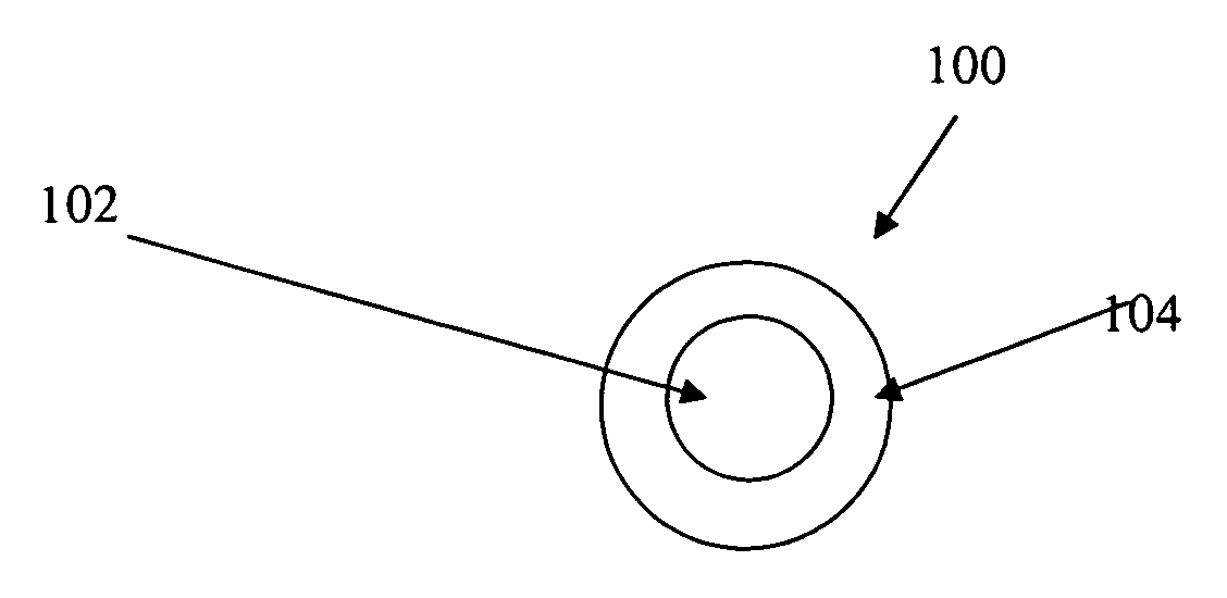
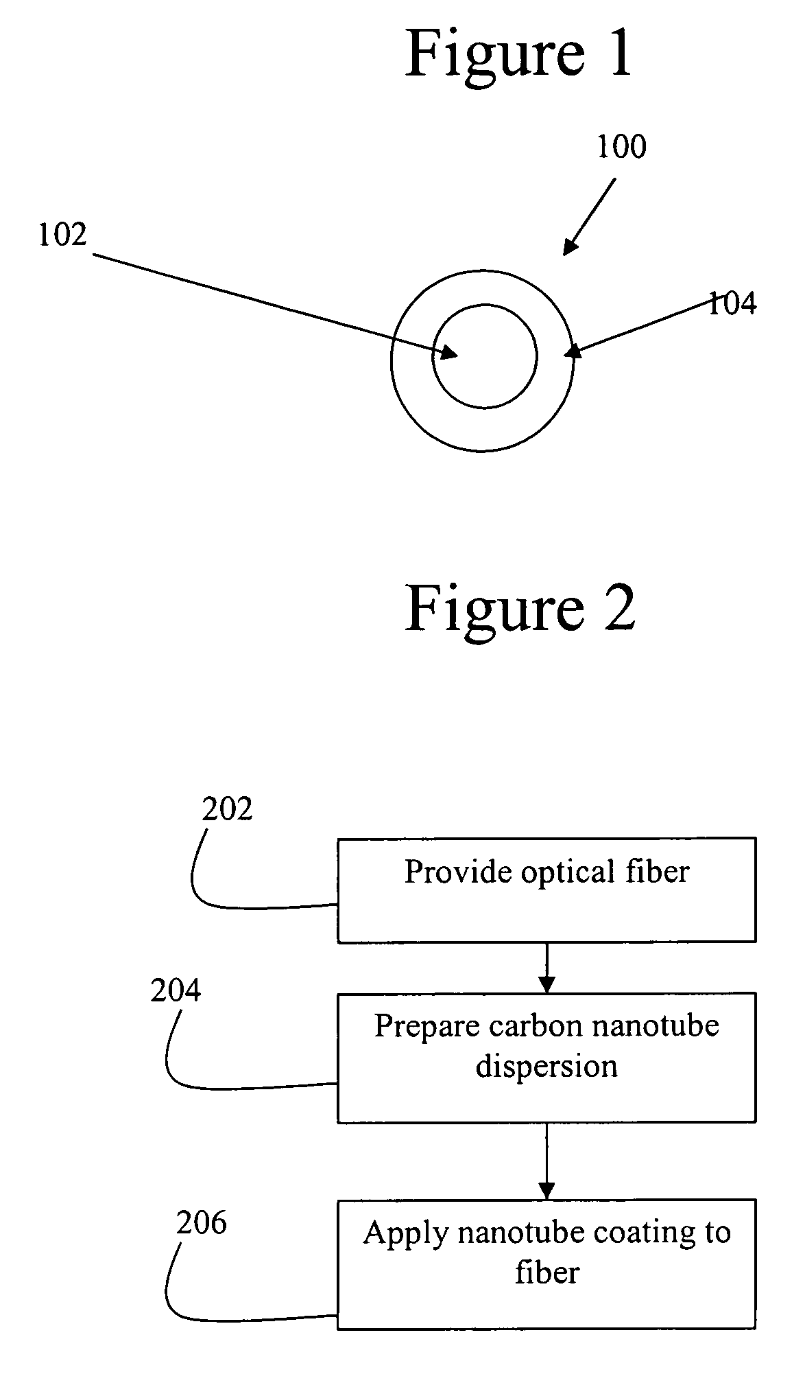
[0035]FIG. 1 shows a cross section of a coated optical fiber 100 according to the preferred embodiment. The coated optical fiber 100 includes an optical fiber 102 having a carbon nanotube containing film 104 applied thereto.

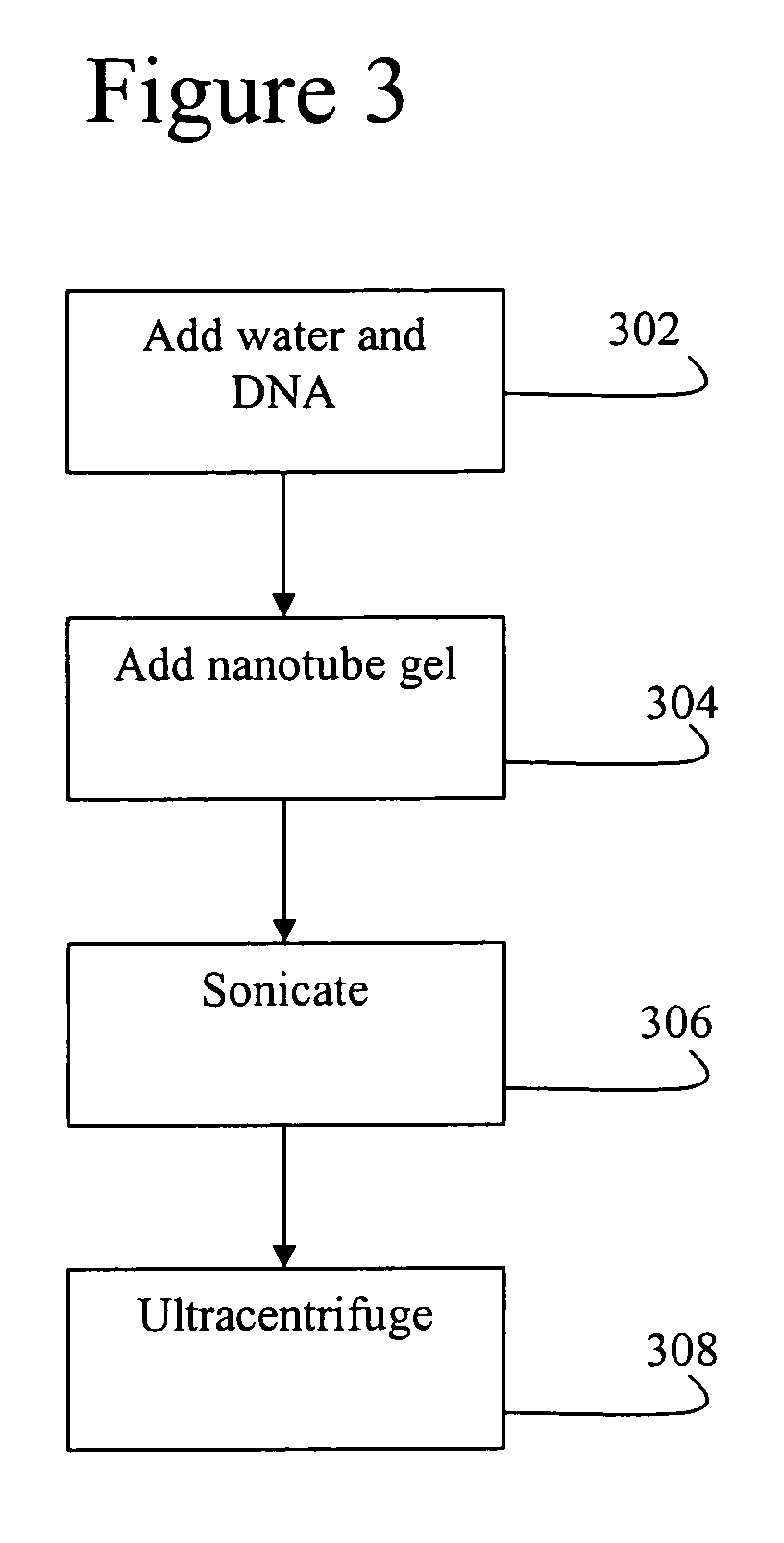
[0036]FIG. 2 is a flow chart showing a technique for applying the carbon nanotube film 104 of FIG. 1. In step 202, the optical fiber 102 is provided. In step 204, a carbon nanotube dispersion is prepared. In step 206, the dispersion is used to apply a carbon nanotube coating 104 to the fiber 102 to form the coated fiber 100.

[0037]A preferred process for carrying out step 204 of forming the dispersion has been developed as part of the present invention to overcome a known problem with nanotube films. More specifically, in applying a nanotube film, there is the problem that is a...


PUM

PropertyMeasurementUnit
Lengthaaaaaaaaaa
Dispersion potentialaaaaaaaaaa
Hydrophobicityaaaaaaaaaa

Abstract

An optical fiber is coated with a super-hydrophobic carbon nanotube film, or other film containing a nanocomposite material, to increase reliability. The film is formed from a carbon nanotube dispersion, which is in turn formed from a mixture of water, carbon nanotube gel, and a polymer such as single stranded DNA of a repeating sequence of the base pairs GT with a length of 20 base pairs, which is sonicated and then ultracentrifuged.

Description

REFERENCE TO RELATED APPLICATION[0001]The present application claims the benefit of U.S. Provisional Patent Application No. 60 / 668,075, filed Apr. 5, 2005, whose disclosure is hereby incorporated by reference in its entirety into the present disclosure.FIELD OF THE INVENTION[0002]The present invention is directed to an optical fiber and more specifically to an optical fiber having thereon a nanocomposite coating or a carbon nanotube containing coating, or a combination of such coatings for increased reliability, service lifetime, wear resistance and environmental protection.DESCRIPTION OF RELATED ART[0003]Fiber optic networks employing wavelength division multiplexing (WDM) technology are desirable for control of aircraft and many other vehicles including undersea vehicles, military tanks and space vehicles. The reliability, inherent tolerance to adverse conditions and immunity to electromagnetic interference or EMI make fiber optic technology a very attractive alternative to conven...

Claims


Application Information

Patent Timeline
IPC IPC(8): B32B1/00C08K3/04
CPCB82Y30/00B82Y40/00C01B31/0273Y10T428/2933C03C25/1075G02B6/02395C03C25/104C01B32/174C03C25/1062
Inventor PETTIT, JOHN W.
Owner PETTIT JOHN W
Why Eureka
Try Eureka