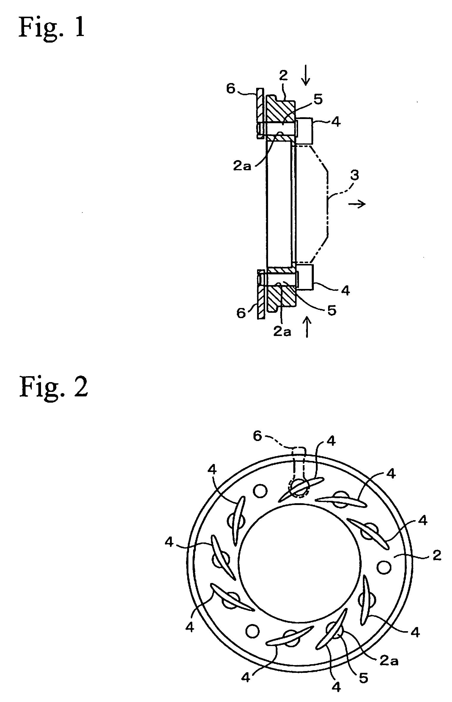
Production method for sintered machine components
a technology of sintered machine components and production methods, which is applied in the direction of engines/engines, mechanical apparatus, engine components, etc., can solve the problems of reduced heat resistance and corrosion resistance of a matrix, difficult to design turbo components for practical use, and insufficient wear resistance, so as to improve heat resistance, corrosion resistance, wear resistance, and high-temperature strength. the effect of strength
- Summary
- Abstract
- Description
- Claims
- Application Information
AI Technical Summary
Benefits of technology
Problems solved by technology
Method used
Image
Examples
first example
[0026]Hereinafter, practical examples of the present invention are described in detail. In the following description, each of the “%” symbols represents “mass %”. An Fe alloy powder A (Fe alloy powder disclosed in Japanese Patent No. 3784003), an Fe alloy powder B, an Fe-20P alloy powder, and a graphite powder were prepared. The Fe alloy powder A consisted of 30% of Cr, 2% of Mo, 2% of Si, and 1% of C, the Fe alloy powder B consisted of 25% of Cr, 20% of Ni, and the balance of Fe and inevitable impurities, and the Fe-20P powder included 20% of P. An amount from 30 to 70% of the Fe alloy powder B was added to the Fe alloy powder A, and 2.5% of the Fe-20P powder and 2.7% of the graphite powder were added thereto, whereby a mixed powder was obtained. The mixed powder was compacted at a compacting pressure of 600 MPa into a pillar shape having an outer diameter of 10 mm and a height of 10 mm, whereby a green compact was obtained. The green compact was sintered at 1200° C. for 60 minutes...
second example
[0029]Fe alloy powder B having a composition shown in Table 2 was prepared. Then, 50% of the Fe alloy powder B, 2.5% of the Fe-20P powder, and 2.7% of the graphite powder were added to the Fe alloy powder A in the first example, and they were mixed together into a mixed powder. The mixed powder was compacted and was sintered in the same manner as in the first example, whereby samples Nos. 8 to 18 were formed. In these samples, increases in the weights due to oxidation, tensile strength (high-temperature strength), and thermal expansion coefficient were measured in the same manner as in the first example. These results and the results of the sample No. 3 in the first example are shown in Table 2.
TABLE 2OxidizedHigh-amounttemperatureThermalSam-Mixing ratio mass %(Air × 100 hr)strengthexpansionpleFe alloyFe alloy powder BFe—20PGraphiteg / m2(800° C.)coefficientNo.powder AFeCrNipowderpowder700800900MPa10−6 K−1Notes8Balance50.0Balance10.020.02.52.711265227016.4Exceedslower limit ofCr amoun...
third example
[0032]Next, 50% of the Fe alloy powder B in the first example, the Fe-20P powder, and the graphite powder were added to the Fe alloy powder A in the first example, and they were mixed together into a mixed powder. The amounts of the Fe-20P powder and the graphite powder were varied as shown in Table 3. The mixed powder was compacted and was sintered in the same manner as in the first example, whereby samples Nos. 19 to 31 were formed. In these samples, increases in the weights due to oxidation, tensile strength (high-temperature strength), and thermal expansion coefficient were measured in the same manner as in the first example. These results and the results of the sample No. 3 in the first example are shown in Table 3.
TABLE 3OxidizedHigh-Mixing ratio mass %amounttemperatureThermalFe alloyFe alloy(Air × 100 hr)strengthexpansionSamplepowder Apowder BFe—20PGraphiteg / m2(800° C.)coefficientNo.(Fe—30Cr—2Mo—2Si—1C)(Fe—25Cr—20Ni)powderpowder700800900MPa10−6 K−1Notes19Balance50.02.50.31351...
PUM
| Property | Measurement | Unit |
|---|---|---|
| Fraction | aaaaa | aaaaa |
| Fraction | aaaaa | aaaaa |
| Fraction | aaaaa | aaaaa |
Abstract
Description
Claims
Application Information
 - R&D
- Intellectual Property
- Life Sciences
- Materials
- Tech Scout
- Unparalleled Data Quality
- Higher Quality Content
- 60% Fewer Hallucinations
Browse by: Latest US Patents, China's latest patents, Technical Efficacy Thesaurus, Application Domain, Technology Topic, Popular Technical Reports.
© 2025 PatSnap. All rights reserved.Legal|Privacy policy|Modern Slavery Act Transparency Statement|Sitemap|About US| Contact US: help@patsnap.com

