
Industrial Process for Producing High-Purity Diol

a technology of industrial process and diol, which is applied in the direction of oxygen-containing compound preparation, sustainable manufacturing/processing, and separation processes, etc., can solve the problems of insufficient purity of ethylene glycol, fatal drawback of process as industrial production process, and further increase of difficulties. , to achieve the effect of high yield, high selectivity and high yield

Inactive Publication Date: 2009-10-29
ASAHI KASEI CHEM CORP
View PDF5 Cites 14 Cited by
  • Summary
  • Abstract
  • Description
  • Claims
  • Application Information

AI Technical Summary

Benefits of technology

[0036]It has been found that according to the specific apparatus and process provided by the present invention, a high-purity diol can be produced from a cyclic carbonate and an aliphatic monohydric alcohol stably for a prolonged period of time on an industrial scale with a high yield (e.g. generally not less than 97%, preferably not less than 98%, more preferably not less than 99%, based on the cyclic carbonate used). That is, according to the present invention, there can be provided an industrial apparatus and industrial production process that are inexpensive and, for example, enable a high-purity diol of purity not less than 99.9% as required as a starting material for a PET fiber or a PET resin to be produced in an amount of not less than 1 ton / hr, preferably not less than 2 tons / hr, more preferably not less than 3 tons / hr, stably for a prolonged period of time (e.g. not less than 1000 hours, preferably not less than 3000 hours, more preferably not less than 5000 hours).
[0037]Moreover, the process according to the present invention differs from a conventional ethylene glycol production process in that high-purity ethylene glycol can be produced by the process according to the present invention with a high yield and a high selectivity without using a large amount of water, and thus achieves excellent effects as an industrial production process that simultaneously solves two long-standing problems with the conventional industrial production process (low selectivity, high energy use).

Problems solved by technology

However, reactive distillation processes proposed hitherto have related to producing the dialkyl carbonate and the diol either in small amounts or for a short period of time, and have not related to carrying out the production on an industrial scale stably for a prolonged period of time.
However, even at the time of filing the present application, there is not the above fact at all.
In particular, the low selectivity indicates that this process has a fatal drawback as an industrial production process.
With such a reactive distillation process, there are very many causes of fluctuation such as composition variation due to reaction and composition variation due to distillation in the distillation column, and temperature variation and pressure variation in the column, and hence continuing stable operation for a prolonged period of time is often accompanied by difficulties, and in particular these difficulties are further increased in the case of handling large amounts.
That is, with the process of Patent Document 15 (Japanese Patent Application Laid-Open No. 2003-342209), ethylene glycol is obtained from a side cut outlet installed in the stripping section, which is below an inlet for feeding into the distillation column, but the purity of the ethylene glycol is insufficient, and moreover the process of Patent Document 15 (Japanese Patent Application Laid-Open No. 2003-342209) is a process in which a small amount of ethylene glycol is produced, there being no suggestions whatsoever regarding a process for producing a large amount (e.g. not less than 1 ton / hr) of a diol stably for a prolonged period of time (e.g. not less than 5000 hours).
A large amount of water must thus be distilled off in an EG purification step, and a large amount of thermal energy is consumed in this .

Method used


Image

  • Industrial Process for Producing High-Purity Diol
  • Industrial Process for Producing High-Purity Diol
  • Industrial Process for Producing High-Purity Diol

Examples


example 1

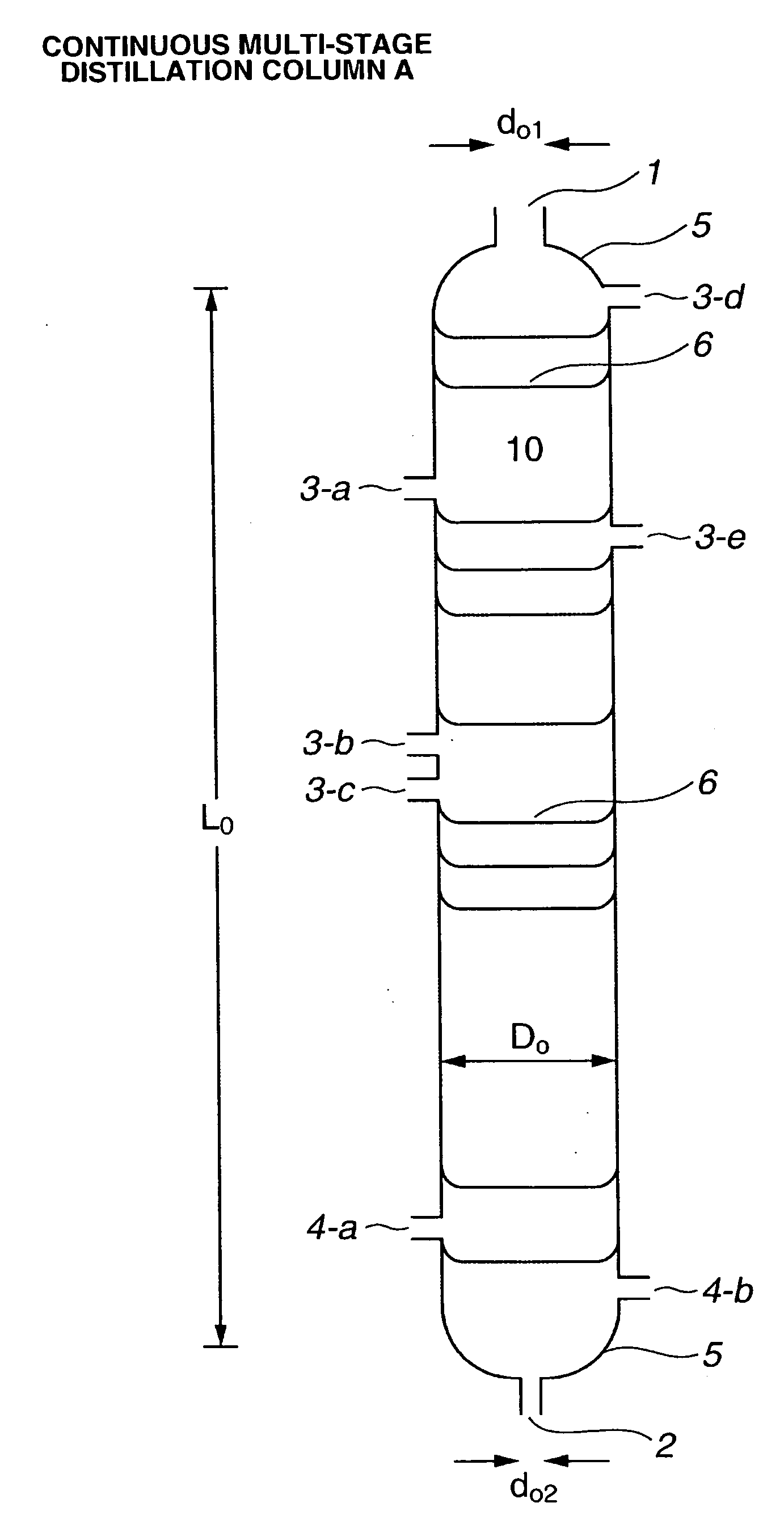
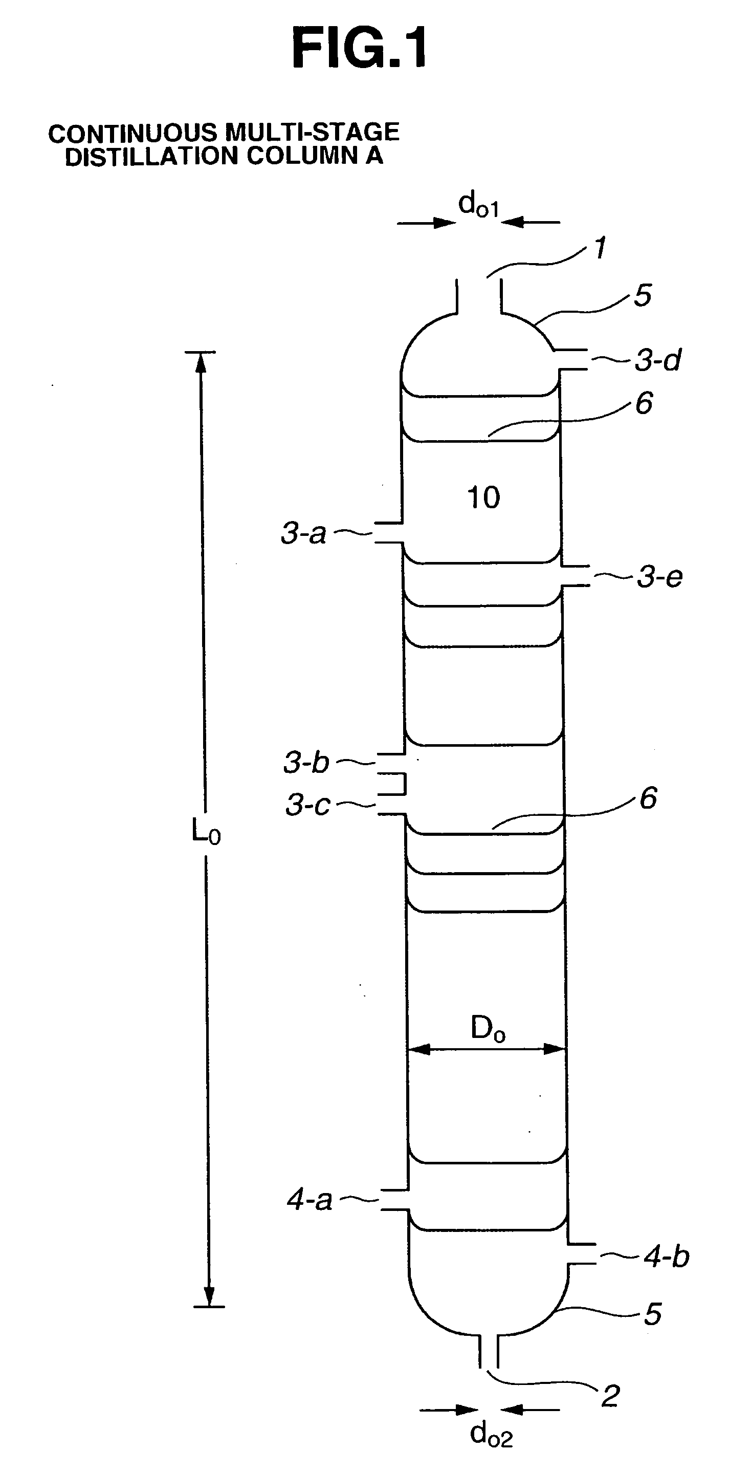
[0196]As the continuous multi-stage distillation column A, a continuous multi-stage distillation column as shown in FIG. 1 having L0=3300 cm, D0=300 cm, L0 / D0=11, n0=60, D0 / d01=7.5, and D0 / d02=12 was used. The trays in the distillation column were sieve trays, each having a cross-sectional area per hole in the sieve portion thereof of approximately 1.3 cm2 and a number of holes of approximately 180 to 320 / m2. The weir height of each of the trays in stages above a stage where the cyclic carbonate was fed in (the 55th stage from the bottom) was 5 cm, and the weir height of each of the trays in stages at and below the stage where the cyclic carbonate was fed in was 6 cm. Moreover, the aperture ratio of each of the trays was in a range of from 2.1 to 4.2%.

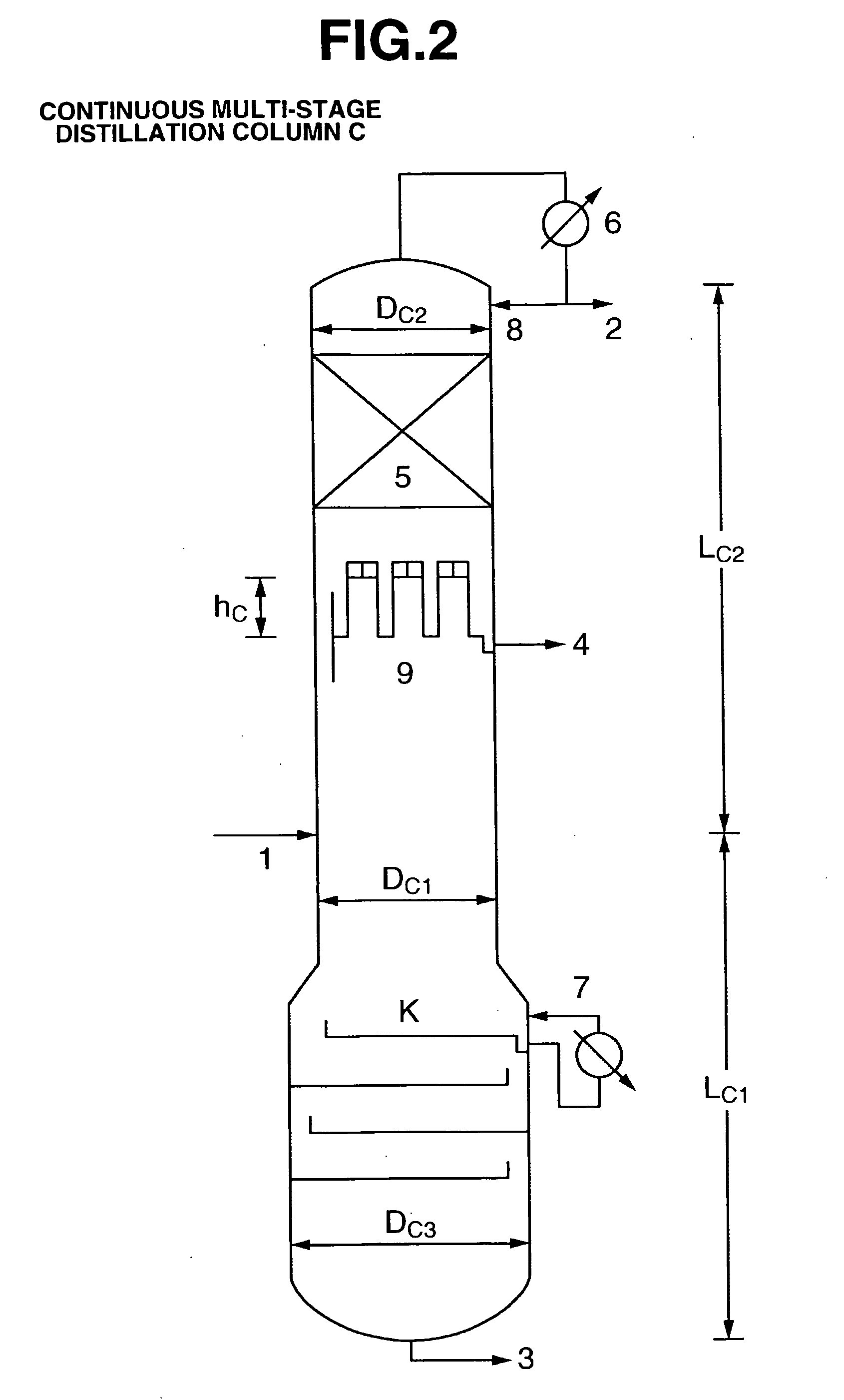
[0197]As the continuous multi-stage distillation column C, a continuous multi-stage distillation column as shown in FIG. 2 having LC1=1100 cm, DC1=110 cm, LC1 / DC1=10, nC1=10, LC2=3000 cm, DC2=110 cm, LC2 / DC2=27.3, and nC2=60 was used. ...

example 2

[0208]High-purity ethylene glycol was produced using the same continuous multi-stage distillation column A, continuous multi-stage distillation column C and continuous multi-stage distillation column E as in Example 1 and a similar process.

[0209]A starting material containing ethylene carbonate (3.565 ton / hr) and methanol (molar ratio MeOH / EC=8) and a catalyst (KOH in ethylene glycol subjected to thermal dehydration treatment; K concentration 0.1% by weight based on EC) was continuously fed into a continuous multi-stage distillation column A, and reactive distillation was carried out, whereby dimethyl carbonate and ethylene glycol were produced with similar reaction results to in Example 1, a column bottom component AB having ethylene glycol as a main component thereof being continuously withdrawn. The column bottom temperature was 93° C., the column top pressure was approximately 1.046×10⁵ Pa, and the reflux ratio was 0.48. The ethylene glycol was separated out by distillation usin...

example 3

[0215]As the continuous multi-stage distillation column A, a distillation column very similar to that used in Example 1 was used. However, each of the sieve trays had a cross-sectional area per hole in the sieve portion thereof of approximately 1.3 cm2 and a number of holes of approximately 240 to 360 / m2. The weir height of each of the trays in stages above the stage where the cyclic carbonate was fed in (the 55th stage from the bottom) was 5 cm, and the weir height of each of the trays in stages at and below the stage where the cyclic carbonate was fed in was 10 cm. Moreover, the aperture ratio of each of the trays was in a range of from 3.0 to 5.0%.

[0216]As the continuous multi-stage distillation column C, a distillation column very similar to that used in Example 1 was used. However, the number of holes in each of the sieve trays in the stripping section and the enrichment section was approximately 550 to 650 / m2, and the aperture ratio was in a range of from 6.5 to 8.5%. Moreover...


PUM

PropertyMeasurementUnit
Temperatureaaaaaaaaaa
Fractionaaaaaaaaaa
Fractionaaaaaaaaaa

Abstract

It is an object of the present invention to provide a specific apparatus and process for industrially producing a high-purity diol by taking a cyclic carbonate and an aliphatic monohydric alcohol as starting materials. Moreover, it is an object to thus provide a specific industrial apparatus and industrial production process that are inexpensive and, for example, enable the high-purity diol to be produced in an amount of not less than 1 ton / hr, preferably not less than 2 tons / hr, more preferably not less than 3 tons / hr, stably for a prolonged period of time (e.g. not less than 1000 hours, preferably not less than 3000 hours, more preferably not less than 5000 hours). According to the present invention, the above objects can be attained by using a continuous multi-stage distillation column A, a continuous multi-stage distillation column C, and a continuous multi-stage distillation column E, which have a specified structure, and withdrawing a liquid component from the side cut outlet, which is installed at the bottom of a chimney tray having a specified structure installed in an enrichment section of the continuous multi-stage distillation column E.

Description

TECHNICAL FIELD[0001]The present invention relates to an industrial process for producing a high-purity diol in which a cyclic carbonate and an aliphatic monohydric alcohol are continuously fed into a reactive distillation column A having a specific structure, reactive distillation is carried out, and a high boiling point reaction mixture having the diol as a main component thereof is continuously withdrawn from the bottom of the reactive distillation column A, material having a lower boiling point than that of the diol is distilled off from the high boiling point reaction mixture using a continuous multi-stage distillation column C having a specified structure, and a column bottom component from the continuous multi-stage distillation column C is fed into a continuous multi-stage distillation column E having a specified structure, and the high-purity diol is continuously obtained as a side cut component of the column E.BACKGROUND ART[0002]A reactive distillation process for produci...

Claims


Application Information

Patent Timeline
IPC IPC(8): C07C31/20C07C29/80B01J10/00
CPCB01D3/009B01D3/146B01D3/32C07C29/128C07C29/80C07C68/065C07C69/96C07C31/202Y02P20/10C07B63/00C07C27/00
Inventor FUKUOKA, SHINSUKEMIYAJI, HIRONORIHACHIYA, HIROSHIMATSUZAKI, KAZUHIKO
Owner ASAHI KASEI CHEM CORP
Learn More