
Vagus nerve stimulation electrodes and methods of use

a vagus nerve and electrode technology, applied in the field of inflammation modulation, can solve the problems of inappropriate or unchecked damage to its own tissues, and the system of stimulation nerves of the inflammatory reflex such as the vagus nerve is generally not appropriate for the stimulation of the vagus nerve, so as to prevent the stimulation of surrounding tissue

Inactive Publication Date: 2009-11-05
FALTYS MICHAEL ALLEN +2
View PDF99 Cites 138 Cited by
  • Summary
  • Abstract
  • Description
  • Claims
  • Application Information

AI Technical Summary

Benefits of technology

[0015]The Cholinergic Anti-inflammatory Pathway (CAP) is a neural pathway in which the efferent vagus nerve regulates systemic cytokine levels through a nicotinic acetylcholine receptor containing the α7 subunit. The response, which attenuates cytokine levels, can be achieved through direct or indirect activation of the corresponding efferent vagus fibers leading the spleen. The CAP can be elicited via afferent or effect pathways using different physical actuator or electrode approaches and locations, and corresponding specific stimulus parameters. Specifically actuators or electrodes are arranged physically to activate the vagal or afferent or efferent fibers or the splenic nerve efferent fibers. These approaches and parameters are designed to: avoid undesirable side effects such as intestinal motility and cardiac effects; elicit a controlled dynamic dose effect as dictated by the system response and pharmacokinetics of anti-inflammatory and pro-inflammatory cytokines; co-modulate both anti-inflammatory and pro-inflammatory cytokines; and not induce a tachyphilaxis.
[0016]Reflex responses diminish in time due to repeated stimulation, an effect termed tachyphilaxis. Tachyphilaxis is avoided by not over stimulating (e.g., overdriving) the CAP. This includes, but is not limited to, stimulating only a brief period every hour or every day of between 10 seconds and 5 minutes, delivering an impulse function to the system (2-10×) threshold for 1-60 seconds between every week and every month, alternating between levels and frequencies every other month (5 Hz at 200% threshold, 20 Hz at 100% of threshold). Tachyphilaxis may be triggered by leads or electrodes that contact the nerve (e.g., nerve cuffs), if they are not appropriately designed, since stimulation of the nerve at the very low levels sufficient to modulate the CAP have been evidenced. Thus the configuration of the electrode or lead, as well as the duration and frequency of bursts should be configured to avoid this effect. This includes surgical cuffs and movement isolation buffers to prevent body movement from being transfers to the lead and the nerve.
[0017]The CAP includes cytokine receptors that are relayed to the brainstem via afferent vagal fibers. The brain activates the vagal cholinergic efferent fibers that terminate in the celiac-superior mesenteric plexus ganglia that then relay to the catecholaminergic nerve fibers that innervate the spleen. In the spleen, those fibers are believed to modulate α7 surface receptors on macrophages, affecting cytokine production of the individual cells and the system. This effect persists for days and may be linked to the lifespan of macrophages (a few days) or a compounded system response. Due to the high profusion rate of macrophages through the spleen, short durations of stimulation reaching the spleen may have long lasting and profound effects on cytokine production. Described herein are several embodiments of neural actuators and leads and associated stimulation parameters to achieve modulation of the inflammatory pathway (e.g., CAP), in a controlled and desired fashion.
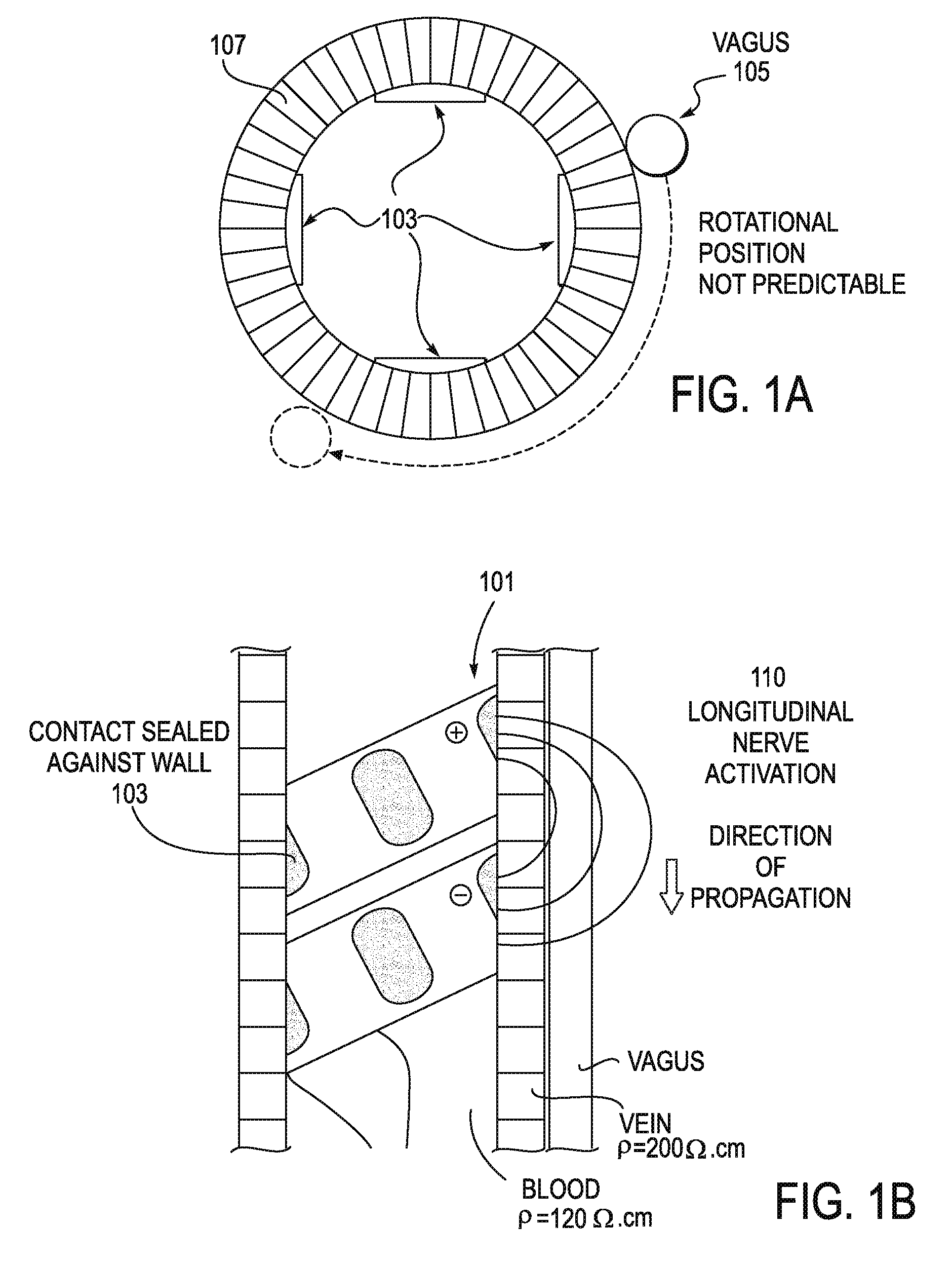
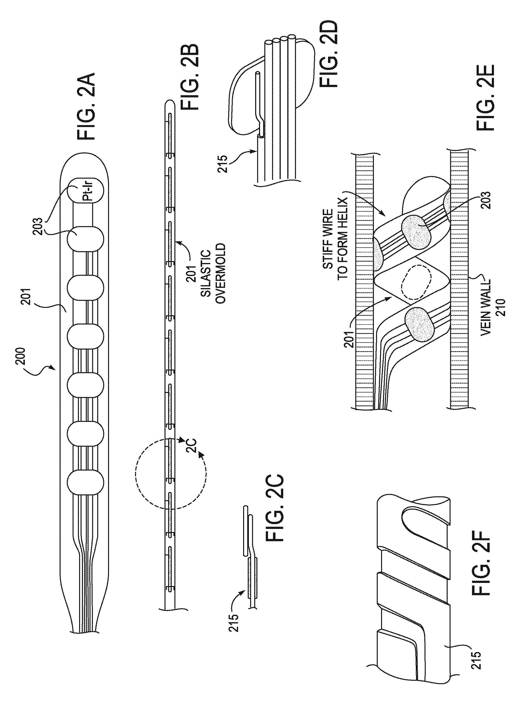
[0024]The method may also include the step of confirming that each of the electrodes on the flexible lead are secured against the wall of the blood vessel. In this variation, the electrodes are oriented against the wall of the vessel (aimed “outward”) and the back of the lead (and electrodes) that faces within the vessel is insulated, to prevent loss of current. The connection between the wall of the vessel and the electrodes can be confirmed by testing the impedance of each electrode. A low impedance may indicate that blood from the lumen of the vessel is contacting the electrode surface. In some variations the electrodes may be further ‘pushed’ against the wall of the vessel by further expanding the lead. In some variations, when a low-impedance electrode is detected, it may be removed from the pool of potential stimulation electrodes.
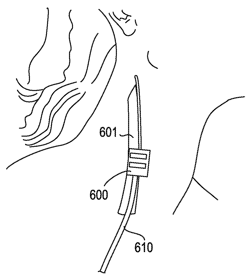
[0032]The step of positioning the carotid sheath cuff lead around the carotid sheath may performed by surgically cutting down to the carotid sheath. In some variations, the carotid sheath cuff is sutured around the carotid sheath. The carotid sheath cuff may be insulated on the outer surface of the cuff to prevent stimulation of surrounding tissue.

Problems solved by technology

However, inappropriate or unchecked inflammation can also lead to a variety of disease states, including diseases such as hay fever, atherosclerosis, arthritis (rheumatoid, bursitis, gouty arthritis, polymyalgia rheumatic, etc.), asthma, autoimmune diseases, chronic inflammation, chronic prostatitis, glomerulonephritis, nephritis, inflammatory bowel diseases, pelvic inflammatory disease, reperfusion injury, transplant rejection, vasculitis, myocarditis, colitis, etc.
In autoimmune diseases, for example, the immune system inappropriately triggers an inflammatory response, causing damage to its own tissues.
Currently available systems for stimulating nerves of the inflammatory reflex such as the vagus nerve are generally not appropriate for stimulation of the vagus nerve to regulate inflammation.
However, none of these publications teach or suggest stimulating the inflammatory reflex, including the vagus nerve, using a system or method that would prevent desensitization of the inflammatory reflex.
Thus cuff electrodes or electrodes implanted to contact the nerve directly may desensitize the modulation of the inflammatory reflex.
Outside of the prescribed ranges of stimulation seen at a nerve of the inflammatory reflex, the resulting stimulation may not be effective, and may inhibit correct stimulation (e.g., by desensitization).

Method used


Image

  • Vagus nerve stimulation electrodes and methods of use
  • Vagus nerve stimulation electrodes and methods of use
  • Vagus nerve stimulation electrodes and methods of use

Examples


Embodiment Construction

[0044]The stimulator configurations and methods of inserting them, as well as systems including them are intended for use in modulating the inflammatory reflex, which may also be described as modulating the Cholinergic Anti-inflammatory Pathway (CAP). A stimulator may include a lead (e.g., an electrical lead) and a controller for regulating the energy applied to the subject by the lead. In some variations the stimulator may also include a power source or power supply providing power to the controller, and for acting as the source of energy applied by the lead. Since, in general, the energy applied to the CAP to modulate the inflammatory reflex is much lower than the energy applied to modulate other vagus effects (such as heart rate, blood pressure, intestinal response, etc.), the source of energy and / or the controller may be substantially smaller and more compact than existing vagus nerve stimulators, for example.

[0045]In general, the systems (e.g., a stimulator) described herein ma...


PUM


Abstract

Described herein are systems, method and devices for modulating the cholinergic anti-inflammatory pathway. The systems described herein may include one or more implantable leads configured to be used to stimulate the inflammatory reflex. These leads typically include a flexible body region, a plurality of electrodes (or contacts) and may be used with a stylet or other inserter. The leads may also include one or more anchors. Exemplary leads may be intra-carotid sheath field-effect leads (“sheath FE” leads), carotid sheath cuff leads (“sheath cuff” leads), intracardiac leads, vagus nerve cuff leads (“vagus cuff” leads), and intravenous leads (“intravascular” leads). Leads (e.g., intravascular leads) may be chronic or acute.

Description

CROSS REFERENCE TO RELATED APPLICATIONS[0001]This patent application claims priority to U.S. Provisional Patent Application Ser. No. 61 / 049,740 field May 1, 2008, titled “VAGUS NERVE STIMULATION ELECTRODES AND METHODS.”[0002]This patent application may also be related U.S. Pat. No. 6,610,713, filed on May 15, 2001 and titled “INHIBITION OF INFLAMMATORY CYTOKINE PRODUCTION BY CHOLINERGIC AGONISTS AND VAGUS NERVE STIMULATION”; pending U.S. patent application Ser. No. 11 / 807,493, filed on Feb. 26, 2003 and titled “INHIBITION OF INFLAMMATORY CYTOKINE PRODUCTION BY STIMULATION OF BRAIN MUSCARINIC RECEPTORS”; pending U.S. patent application Ser. No. 10 / 446,625, with a priority date of May 15, 2001 and titled “INHIBITION OF INFLAMMATORY CYTOKINE PRODUCTION BY CHOLINERGIC AGONISTS AND VAGUE NERVE STIMULATION”; and pending U.S. patent application Ser. No. 11 / 318,075, filed on Dec. 22, 2005 and titled “TREATING INFLAMMATORY DISORDERS BY ELECTRICAL VAGUS NERVE STIMULATION.” This provisional pa...

Claims


Application Information

Patent Timeline
Patent Type & Authority Applications(United States)
IPC IPC(8): A61N1/36
CPCA61N1/0553A61N1/0556A61N1/36053A61N1/36114A61N2001/0585A61N1/056
Inventor FALTYS, MICHAEL ALLENBRODERICK, JAMES W.TRACEY, KEVIN J.
Owner FALTYS MICHAEL ALLEN
Learn More