
Method for Repairing Cracks in Components and Solder Material for Soldering Components

a technology for components and soldering components, applied in the direction of turbines, manufacturing tools, soldering apparatus, etc., can solve the problems of fatigue cracks, power plant operators or aircraft turbine manufacturers having to calculate relatively high costs, and affecting the properties of components in the region of the repaired si

Inactive Publication Date: 2009-11-19
MTU AERO ENGINES GMBH
View PDF5 Cites 19 Cited by
  • Summary
  • Abstract
  • Description
  • Claims
  • Application Information

AI Technical Summary

Benefits of technology

[0014]It is an object of the present invention to provide a method which is advantageous relative to the prior art for repairing components which consist of a superalloy, in particular a superalloy having a directional microstructure.
[0015]It is another object of the present invention to provide a solder material which may advantageously be used for soldering superalloys, in particular for soldering superalloys having a directional microstructure.
[0023]The method according to the invention makes it possible to obviate the additional elements that lower the melting point, and in particular to obviate boron or silicon which may lead to the brittle phases mentioned in the introduction. The method according to the invention makes it possible in particular to lower the melting temperature of solder materials for superalloys based on nickel, cobalt or iron, which comprises at least one of the elements Al (aluminum), Ti (titanium), Ta (tantalum), Cr (chromium), Co (cobalt), Mo (molybdenum), W (tungsten), Nb (niobium) as main alloy elements. The melting temperature of the solder material may be lowered relative to the melting temperature of the superalloy for example when the proportion of at least one of the elements Al, Ti, Ta, Nb in the alloy of the solder material is increased relative to its proportion in the superalloy and / or the proportion of the element W in the alloy of the solder material is reduced relative to its proportion in the superalloy. It is also preferable to use only Al and Ti.
[0026]A solder material according to the invention for soldering components which consist of a superalloy, particularly a superalloy having a directional microstructure, is an alloy having the same alloy constituents as the alloy of the component. In the solder material according to the invention, at least one proportion of an alloy constituent in the composition of the solder material is modified relative to its proportion in the composition of the alloy of the component such that the melting temperature of the solder material is lowered relative to the melting temperature of the alloy of the component. It is therefore possible to substantially obviate the element that lowers the melting point in the solder, which may lead to the brittle phases mentioned in the introduction, in particular boron or silicon. The solder material is suitable in particular for carrying out the method according to the invention.
[0040]The proportions of Ta and / or Ti in the alloy of the solder material are then increased relative to the composition of the superalloy, so that the melting temperature of the solder material is lowered relative to the superalloy.

Problems solved by technology

Owing to the usually extremely complex blade design and the relatively low suitability of such alloys for being shaped, turbine blades are produced by the vacuum casting method.
Besides great material losses due to corrosion, fatigue cracks in particular are the most frequently occurring reasons for replacement of the components.
Particularly in the case of rotor blades, such fatigue cracks occur transversely to the blade longitudinal axis.
Owing to the high material and production costs for turbine components having a directional microstructure, a power plant operator or a manufacturer of aircraft turbines must calculate in relatively high costs, for example to replace turbine blades, for the maintenance of a gas turbine system.
Boron, however, may lead to the formation of brittle borides which impair the properties of the component in the region of the repaired site.
Furthermore, the method is not suitable for gap widths of more than about 200 μm.
Constituents that lower the melting point are also added to the solder product in this case, which for example in the case of boron may negatively affect the properties of the repaired site.

Method used


Image

  • Method for Repairing Cracks in Components and Solder Material for Soldering Components
  • Method for Repairing Cracks in Components and Solder Material for Soldering Components
  • Method for Repairing Cracks in Components and Solder Material for Soldering Components

Examples


Embodiment Construction

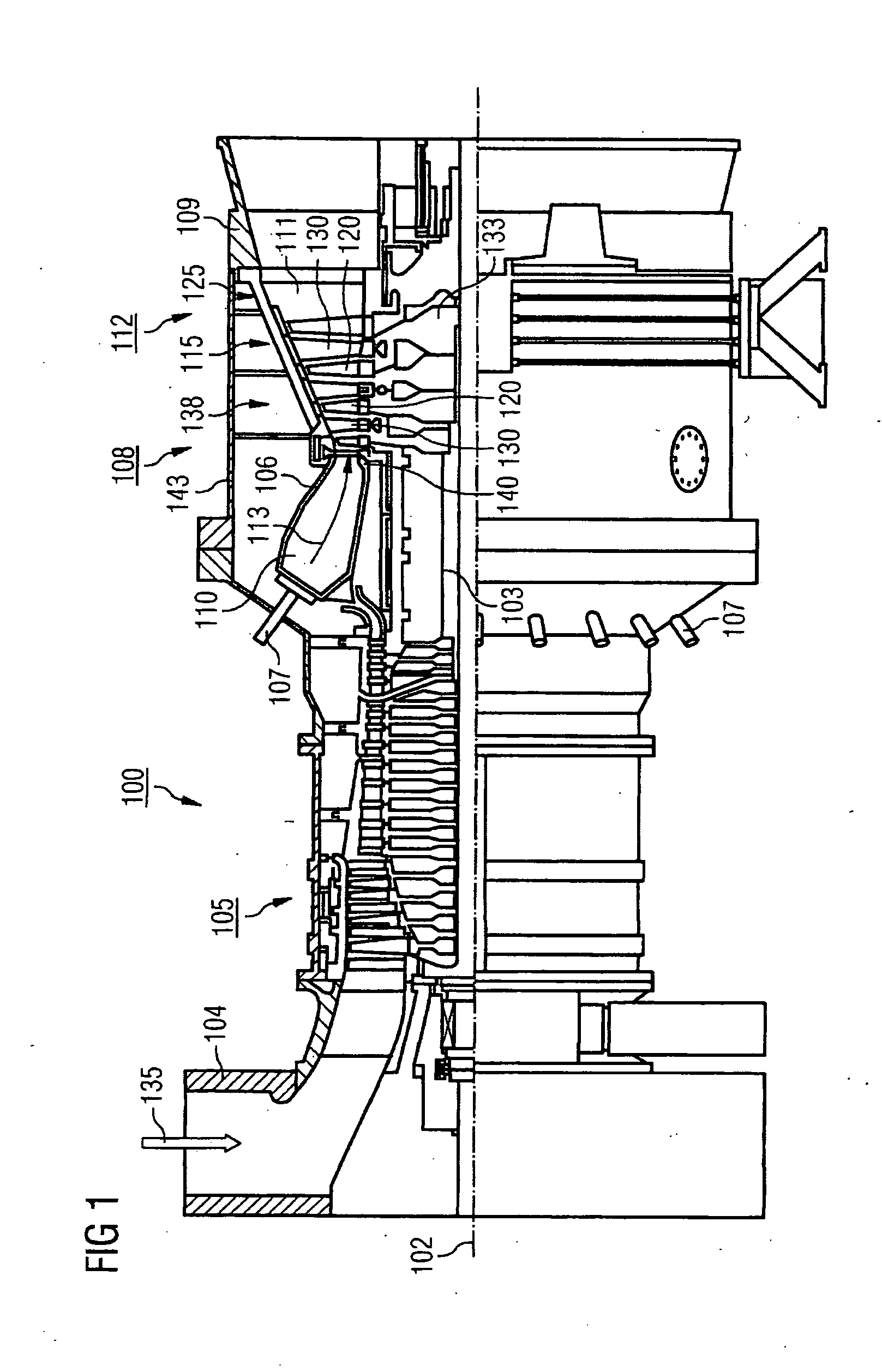
[0047]FIG. 1 shows a gas turbine 100 by way of example in a partial longitudinal section. The gas turbine 100 internally comprises a rotor 103, which will also be referred to as the turbine rotor, mounted so as to rotate about a rotation axis 102. Successively along the rotor 103, there are an intake manifold 104, a compressor 105, an e.g. toroidal combustion chamber 110, in particular a ring combustion chamber 106, having a plurality of burners 107 arranged coaxially, a turbine 108 and the exhaust manifold 109.

[0048]The ring combustion chamber 106 communicates with an e.g. annular hot gas channel 111. There, for example, four successively connected turbine stages 112 form the turbine 108.

[0049]Each turbine stage 112 is formed for example by two blade rings. As seen in the flow direction of a working medium 113, a guide vane row 115 is followed in the hot gas channel 111 by a row 125 formed by rotor blades 120.

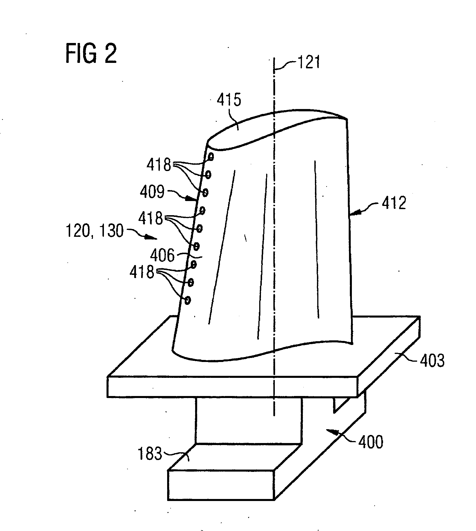
[0050]The guide vanes 130 are fastened on an inner housing 138 of a stato...


PUM

PropertyMeasurementUnit
Fractionaaaaaaaaaa
Fractionaaaaaaaaaa
Fractionaaaaaaaaaa

Abstract

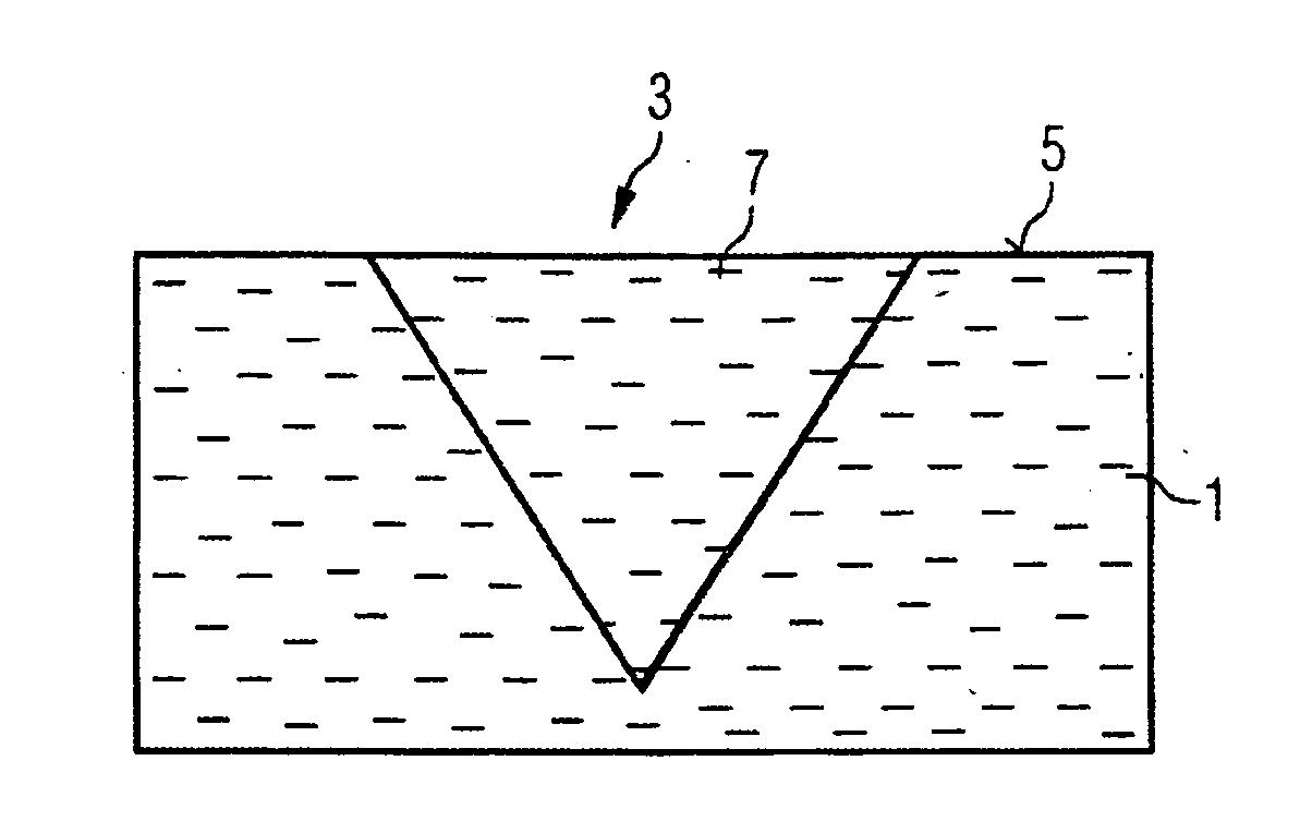
The invention relates to a method for repairing components that consist of superalloys, in particular for repairing components that consist of a superalloy with an aligned microstructure in such a way that the repaired site likewise has an aligned microstructure. The method comprises the following steps: a solder material is applied to the repair site; the repair site with the applied solder material is heated until the latter melts; and the melted solder material is left to solidify. The solder material is an alloy with the same alloy components as the component alloy. At least the fraction of one alloy component in the solder material composition is modified in relation to the fraction of that alloy component in the component alloy composition, in such a way that the melting temperature of the solder material is reduced in relation to the melting temperature of the component alloy.

Description

CROSS REFERENCE TO RELATED APPLICATIONS[0001]This application is the US National Stage of International Application No. PCT / EP2006 / 067951, filed Oct. 31, 2006 and claims the benefit thereof. The International Application claims the benefits of European application No. 05025898.7 filed Nov. 28, 2005, both of the applications are incorporated by reference herein in their entirety.FIELD OF INVENTION[0002]The present invention relates to a method for repairing cracks in components which consist of a superalloy, particularly a superalloy having a directional microstructure, the method then in particular being configured so that a repaired crack likewise has a directional microstructure. The invention furthermore relates to a solder material for soldering components which consist of a superalloy, in particular one having a directional microstructure.BACKGROUND OF THE INVENTION[0003]The improvement of aircraft gas turbines and electrical energy generation by means of static gas turbines is...

Claims


Application Information

Patent Timeline
IPC IPC(8): B23K31/02B23K35/24
CPCB23K1/0018B23K1/19B23K35/3033B23K35/304B23K2201/001B23P6/007F05B2230/80C22C19/056C22C19/057C22C19/058C22C19/07C22F1/10F05B2230/238B23P6/045B23K2101/001
Inventor VOLEK, ANDREAS
Owner MTU AERO ENGINES GMBH
Learn More