

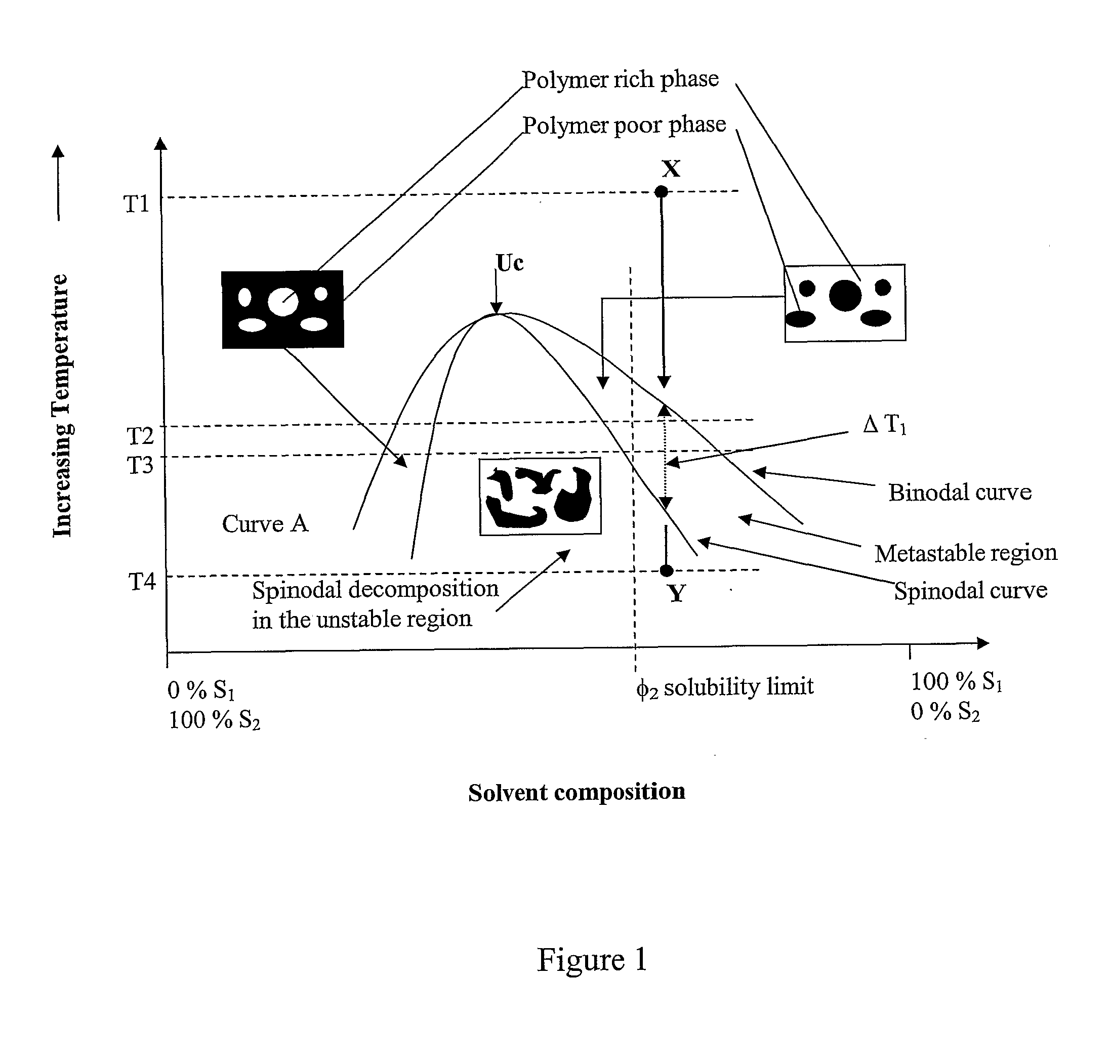
Porous polymer blend structures
a polymer blend and polymer technology, applied in the field of polymer blends, can solve the problems of inferior properties, compositional sharpness and mechanical weakness of interphase interfaces, and the inability to distinguish between polymer components, and achieve excellent physical and mechanical properties, promote molecular mixing, and enhance biocompatibility of polyurethane.
- Summary
- Abstract
- Description
- Claims
- Application Information
AI Technical Summary
Benefits of technology
Problems solved by technology
Method used
Image

Examples
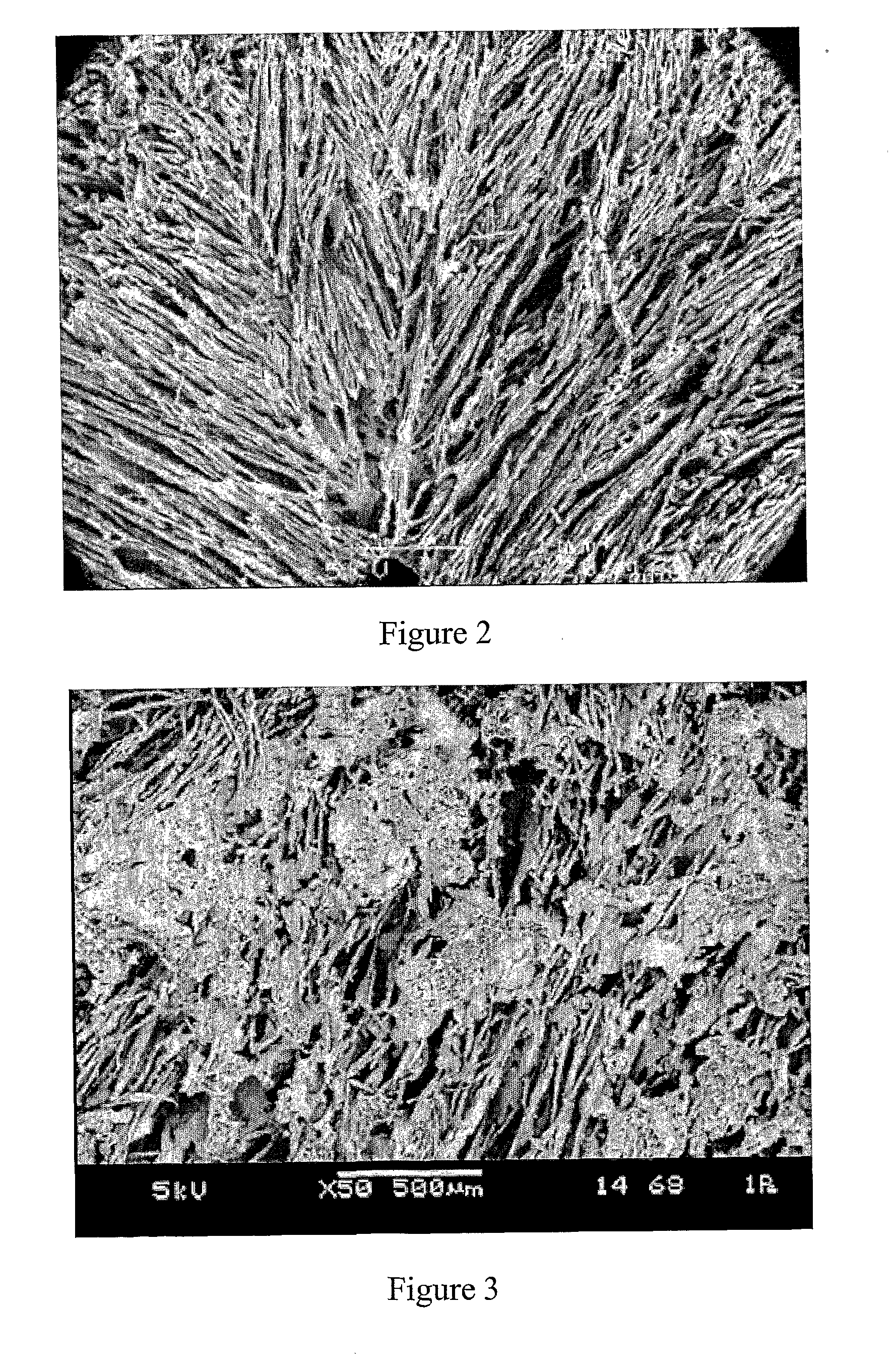
example 1
Formation of a PLGA / PU Porous Polymer Blend Scaffold
[0116]A solution of PLGA / PU in DSMO was prepared by dissolving 75 / 25 PLGA and polyurethane (PU) pellets (ElastEon PU 70A) in dry DMSO at a total polymer concentration of 5% w / w (i.e. 2.5% w / w PLGA, 2.5% w / w PU for the mixed solution).
[0117]The polyurethane pellets used in this example incorporating hard segments comprising 4,4′-methylenediphenyl diisocyanate, a mixture of butanediol and a short siloxane chain extender and soft segments comprising bis(hydroxyalkyl) polydimethyl siloxane (PDMS) and poly(hexamethylene oxide) (PHMO).
[0118]The PLGA / PU solution was heated to 90° C. and stirred for 24 hours to aid dissolution of the polymer to form a homogenous solution, before being pipetted into a 13 mm diameter glass vials with snap-on lids. The PLGA / PU solution was maintained at a temperature of 90° C. by wrapping an external heating element around the vial. The vial and heating element were then placed in a water bath at 5° C. for 24...
example 2
Formation of a PLGA / PU Porous Polymer Blend Scaffold
[0119]A porous polymer blend scaffold was prepared as in Example 1 except with a slower quenching regime. In particular, the PLGA / PU solution was heated to 90° C. and stirred for 24 hours to aid dissolution of the polymer to form a homogenous solution before being pipetted into a 13 mm diameter glass vials with snap-on lids. The PLGA / PU solution was maintained at a temperature of 90° C. within the vial using a temperature controlled bath. The temperature of the polymer solution within the vial was then reduced from ˜90° C. to ˜60° C. over 20 seconds and thereafter the solution quenched to −5° C. by transferring it into another temperature controlled bath set at −5° C. for 24 hours to freeze or solidify the solution. The vial was then removed from the water bath and placed onto a mesh support in a beaker filled with ice and cold water to leach the DMSO from the solidified solution to result in an interconnected porous polymer blend / ...
examples 3 to 6
Formation of Other Porous Polymer Blend Scaffolds
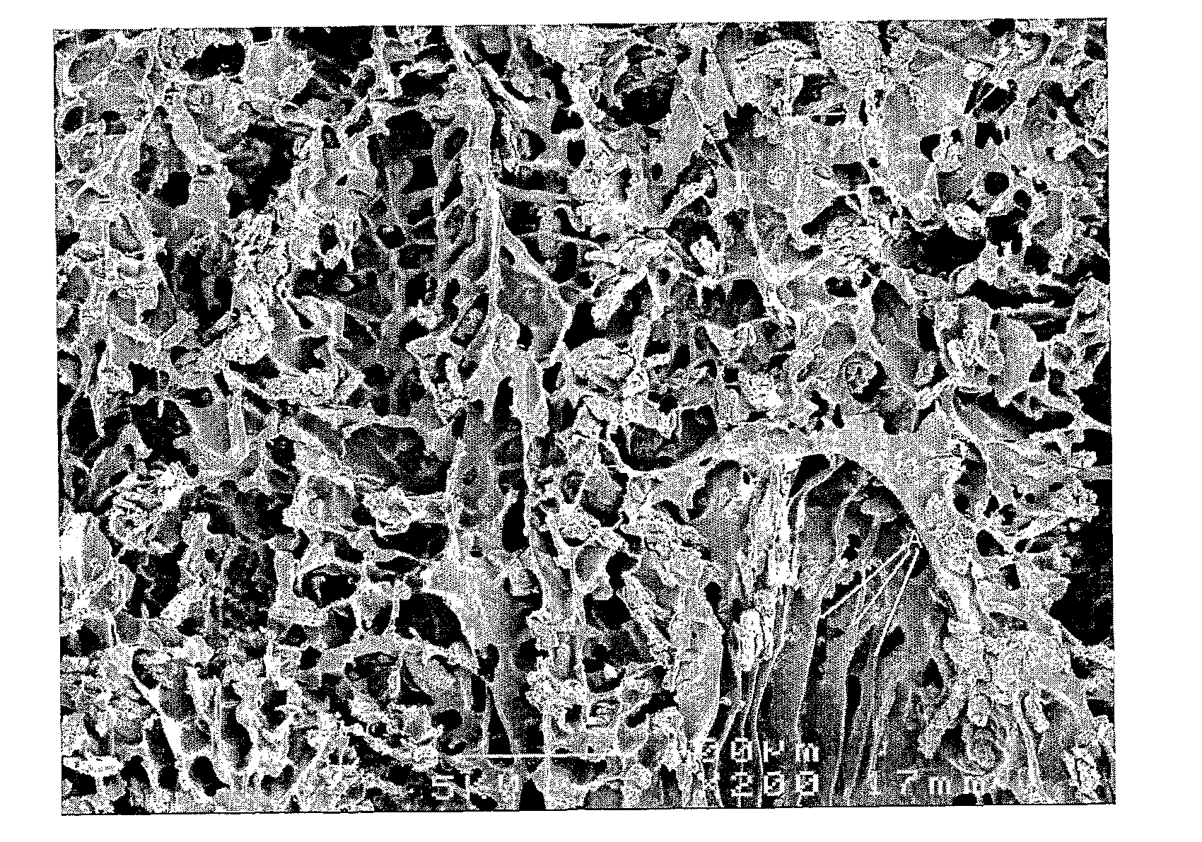
[0120]Porous polymer blends of various structural morphologies were prepared from PLGA, agarose, and DMSO (Example 3); PCL, PLGA, and DMSO (Example 4); PLA, Chitosan and DMSO (Example 5); and PLGA, elastin and 1,4-dioxane (Example 6) liquid compositions in a manner similar to that described in Example 1, above, to result in the porous polymer blend scaffolds shown in FIGS. 4 to 7, respectively.
PUM
| Property | Measurement | Unit |
|---|---|---|
| Percent by volume | aaaaa | aaaaa |
| Percent by volume | aaaaa | aaaaa |
| Percent by volume | aaaaa | aaaaa |
Abstract
Description
Claims
Application Information