Cylindrical membrane apparatus for forming foam

a cylindrical membrane and foam technology, applied in the field of stable foams, can solve the problems of long shelf life of frozen ice cream systems, lack of novel aeration techniques to address the above needs, and inability to manufacture related emulsions or dispersions,

Inactive Publication Date: 2009-12-31
NESTEC SA
View PDF29 Cites 35 Cited by
  • Summary
  • Abstract
  • Description
  • Claims
  • Application Information

AI Technical Summary

Benefits of technology

[0025]In case of the eccentric inner non-membrane cylinder arrangement, the eccentric flow gap has a width ratio of largest gap width to smallest gap width of 1.1 to 5 to provide adjustability in the selection of the gas bubble size or size distribution.

Problems solved by technology

Smaller air cell size also supports longer shelf life of frozen ice cream systems due to increased steric hindrance for ice crystal growth.
Furthermore, novel aeration techniques to address the above need remain lacking.
This is certainly not acceptable for the manufacture of related emulsion or dispersion systems if changes in volume flow rate would also impact on the drop size distribution of the disperse phase thus changing related system properties.
First attempts in membrane foaming have also been introduced using static membrane devices with the same type of problems as described for the liquid / liquid dispersion processing above, however with more pronounced problems concerning the generation of small bubbles in particular at higher gas volume fractions (>30-40%).
The reason is that in spite of easy and large deformation of air bubbles in sheared liquids, there is no efficient break up, or in other words, the critical bubble deformation is strongly increasing with decreasing viscosity ratio.
This is not satisfactory, however, with regard to bubble size and narrow bubble size distribution width.
Even in the turbulent flow domain a laminar Prandt1 layer exists in the vicinity of the walls, thus limiting the turbulent dispersing mechanism.
Recently a rotating membrane device has been introduced for liquid / liquid dispersing showing the high potential of improved drop dispersing in particular with respect to small and narrowly size distributed droplets, but this device has not been used for gas dispersing or foaming.
This is likely due to the problems related to the difficult gas bubble break up in shear dominated laminar flow described above, as well as due to the high density difference between the two phases which makes the process in rotational, particularly laminar flow fields, even more difficult.
Such fundamental problems remain unsolved.
This device is not suitable, however, for the generation of finely dispersed homogeneous gas dispersions or foams due to the large radial dimensions of the dispersing gaps formed between the membrane modules and the housing, which would strongly support the de-mixing of the phases at higher rotational velocity required for the refinement of the gas bubbles.

Method used


Image

  • Cylindrical membrane apparatus for forming foam
  • Cylindrical membrane apparatus for forming foam
  • Cylindrical membrane apparatus for forming foam

Examples


first embodiment

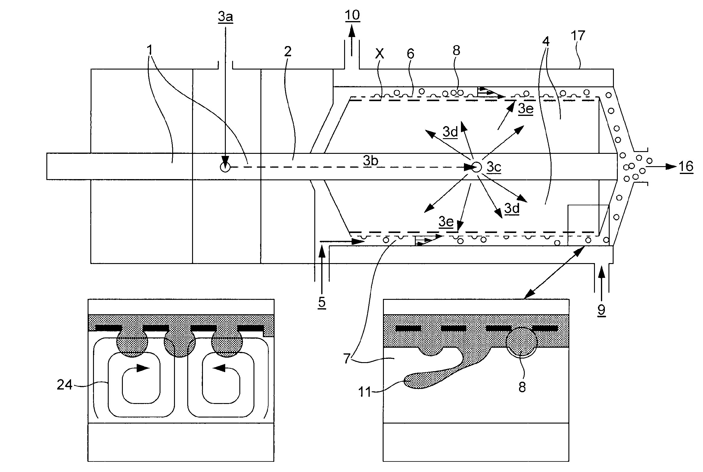
[0210]FIG. 12 shows a schematic diagram of the novel membrane process / device (Type B I) with the membrane mounted on rotating inner cylinder (Type I), in accordance with the invention. In FIG. 12, (1) denotes two double-sided slide ring sealings allowing to delivery of gas / air without leakage through the rotating hollow shaft (2). The gas / air enters the shaft at the gas / air inlet (3a) flows through the inner shaft channel (3b) and leaves the shaft again through holes (3c) into the hollow rotating cylinder (4), which at its surface holds the membrane (6). The gas / air is evenly distributed in the hollow cylinder (3d) and from there pressed through the membrane pores (3e) into the dispersing flow gap (7) forming bubbles at the membrane surface (8) or shooting as gas / air filaments (11) into the gap. The continuous liquid fluid phase enters the dispersing device at the fluid / mix inlet (5). As soon as the fluid / mix enters the dispersing gap (7) the dominating rotational flow component ove...

second embodiment

[0211]FIG. 13 shows additional information for the novel membrane process / device Type B II with the membrane mounted on the fixed housing (Type II), in accordance with the present apparatus. The shaft (2) and the connected cylinder (4) are no longer part of the aeration system. The membrane (6) is mounted onto a cage construction (18) connected to the inner surface of the cylindrical housing (17) and forming a gas / air chamber (19) between the inner housing wall and the membrane. Through a central gas / air inlet (13a) the chamber (19) is supplied with gas / air, which is evenly distributed (13b) and pressed through the membrane pores (13e) into the dispersing gap (7).

[0212]The continuous fluid flow and its impact on the dispersing procedure is expected to be similar to the type I version of the process described above (FIG. 12), except the different impact of the centrifugal forces which in this type II device support more gas phase shooting into the dispersing flow gap, forming prefera...


PUM

PropertyMeasurementUnit
pore diametersaaaaaaaaaa
widthaaaaaaaaaa
circumferential velocityaaaaaaaaaa

Abstract

An apparatus and process for making a foam having a controlled size distribution of gas bubbles in a liquid matrix. The invention utilizes a porous material having a controlled pore size and pore distance to produce a substantially uniform size distribution of gas bubbles; a gas pumping device for directing a flow of gas to and through the porous material to form the gas bubbles; a fluid pumping device for directing a flow of liquid matrix past the porous material and a rotating element moving in the vicinity of the membrane surface causing an additional flow to detach, collect accumulate and entrain the gas bubbles in the liquid matrix to form a foam having gas bubbles of generally uniform size and a substantially uniform gas bubble size distribution. Advantageously, the pore size and pore distance of the porous material, the gas flow from the gas pumping device, the flow field generated by the rotating element and the liquid flow from the fluid pumping device cooperate to provide gas bubbles having a mean diameter X50,0 that is less than 2-2.5 times, preferably less than 1.25-1.5 times the mean pore diameter of the membrane and to provide the foam with a gas bubble diameter distribution ratio X90,0/X10,0 that is less than 5, preferably less than 3.

Description

BACKGROUND OF THE INVENTION[0001]The present invention relates to stable foams having a controlled fine air bubble size distribution and to edible products prepared therefrom having a low fat content. Particularly interesting products prepared from such foams include ice creams and related frozen products.[0002]The manufacture of finely dispersed gas bubbles in a continuous liquid or semi solid fluid phase either denoted as gas dispersions for gas volume fractions below about 10-15%, or as foams for gas volume fractions higher than about 15-20% is of major interest in particular in the food, pharmaceutical, cosmetics, ceramics and building material industries. The gas fraction in related products of these industries has a strong impact on the physical parameters like density, rheology, thermal conductivity and compressibility and related application properties. In the area of foods, aeration of liquid to semi-solid systems adds value with respect to consistency and related perceptio...

Claims


Application Information

Patent Timeline
Patent Type & Authority Applications(United States)
IPC IPC(8): B01F3/04B01F5/04B01F7/00A23P30/40
CPCB01F3/04269B01F3/04453B01F5/0451B01F5/0476B01F2215/0021B01F7/00816B01F7/12B01F2003/04404B01F7/008B01F23/231244B01F23/23124B01F23/2351B01F25/31421B01F25/3131B01F27/272B01F27/2722B01F27/74B01F2101/13
Inventor WINDHAB, ERICH JOSEFMULLER-FISCHER, NADINA PATRIZIATAPFER, KARL UWE
Owner NESTEC SA
Why Eureka
Try Eureka