
Method for cell patterning

a cell patterning and cell technology, applied in the field of cell patterning, can solve the problems of complex process for producing cell culture substrate, difficult to pattern plural kinds of cells onto one substrate, and inefficient cell patterning, etc., to achieve low electric field strength, easy co-culture, and low electric field strength

Inactive Publication Date: 2009-12-31
TOHOKU UNIV
View PDF0 Cites 8 Cited by
  • Summary
  • Abstract
  • Description
  • Claims
  • Application Information

AI Technical Summary

Benefits of technology

[0005]The present invention has been made in consideration of the above-described problems in the conventional techniques. An object of the present invention is to provide a method for cell patterning which: eliminates the need for forming, in advance, a pattern on a cell culture substrate in order to arrange cells; allows cells to be efficiently arranged onto the cell culture substrate in a predetermined pattern; and enables an electrode substrate to be used repeatedly by detaching the electrode substrate from the cell culture substrate.
[0006]The present inventors have earnestly studied in order to achieve the above object. As a result, the inventors have revealed that it is possible: to eliminate the need for forming, in advance, a pattern on a cell culture substrate in order to arrange cells; to efficiently arrange cells onto the cell culture substrate in a predetermined pattern; and to repeatedly use an electrode substrate by detaching the electrode substrate from the cell culture substrate. This is made possible in the following manner. Specifically, by using an electrode substrate including a plurality of electrodes and a cell culture substrate disposed so as to face the electrode substrate, a cell suspension containing cells is introduced into a region between the electrode substrate and the cell culture substrate; a voltage is applied to the electrodes to generate an non-uniform electric field in the region; and the cells are arranged at a position with low electric field strength on the cell culture substrate by utilizing negative dielectrophoresis. This discovery has led the inventors to complete the present invention.
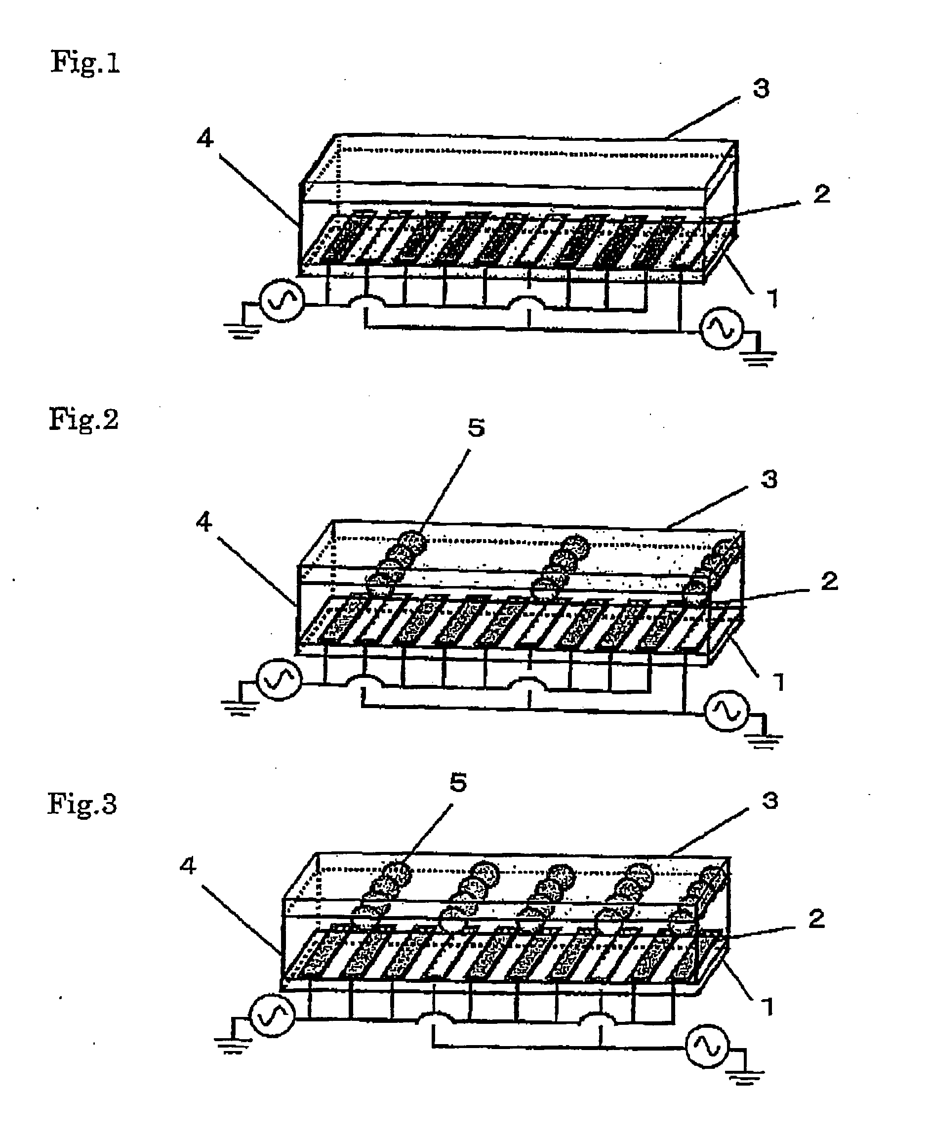
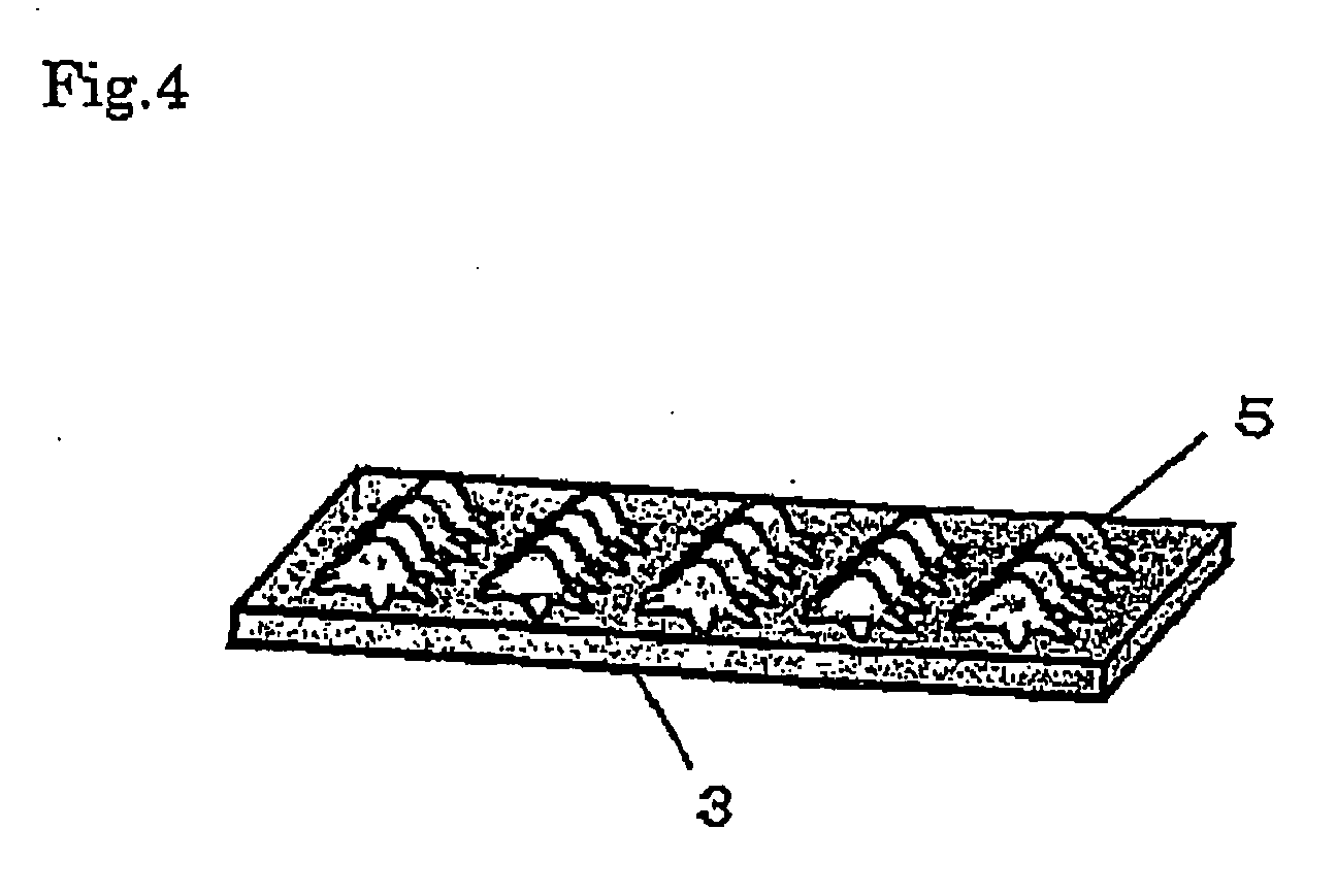
[0012]Here, it is not known exactly why the method for cell patterning of the present invention can achieve the above object. However, the present inventors speculate as follows. Specifically, in the present invention, a cell suspension containing cells is first introduced into the region between the electrode substrate and the cell culture substrate, and an alternating voltage is applied to the region to generate a non-uniform electric field therein. Such application of the voltage induces a dipole moment that is attributable to the difference in polarizability between cells and a solvent. Next, the interaction between the induced dipole moment and a difference in electric field strength results in repulsive forces acting on the cells. Among phenomena in which such repulsive forces act, a phenomenon of negative dielectrophoresis is used to arrange cells onto the cell culture substrate in the present invention. In the negative dielectrophoresis, cells in a region with high electric field strength are guided to a region with low electric field strength when subjected to repulsive forces. Thus, in the present invention, it is possible to arrange cells at a position with low electric field strength in a predetermined pattern without conducting a special pre-treatment on the cell culture substrate. Further, in the present invention, cells are guided to the region with low electric field strength and arranged therein. Thus, the pattern into which the cells are arranged can be changed easily, by controlling the combination of electrodes to which a voltage is applied and appropriately changing the position with low electric field strength. Moreover, when multiple cell suspensions are prepared and introduced one after another and then the position with low electric field strength is changed appropriately to arrange the cells, it is further possible to arrange easily and separately plural kinds of cells at any positions, which allows an easy patterned co-culture of the plural kinds of cells. Furthermore, in the present invention, the cell culture substrate on which cells are to be arranged and the electrode substrate are separated, and the cells are arranged onto the cell culture substrate. Thus, the electrode substrate can be used repeatedly.
[0013]The present invention can provide a method for cell patterning which; eliminates the need for forming, in advance, a pattern on a cell culture substrate in order to arrange cells; allows cells to be efficiently arranged onto the cell culture substrate in a predetermined pattern; and enables an electrode substrate to be used repeatedly by detaching the electrode substrate from the cell culture substrate. Further, the present invention makes it possible to arrange plural kinds of cells in a predetermined pattern, which allows a patterned co-culture of the plural kinds of cells.

Problems solved by technology

In the method for cell patterning described in Document 1, however, a process for producing the cell culture substrate is complicated, and cells are not efficiently patterned.
In addition, with the method as described in Document 1, it is difficult to pattern plural kinds of cells onto one substrate.
As for the cell culture substrates as described in Documents 2 and 3, the production processes thereof are complicated, because it is necessary to form a micrometer-order pattern on these substrates in production of these substrates.
Moreover, when such a substrate as described in Document 2 or 3 is used, it is also difficult to pattern plural kinds of cells onto one substrate.
Accordingly, it is difficult to reuse the electrode substrate.
In addition, when cells are patterned by using the method as described Document 4 or 5, it is difficult to pattern plural kinds of cells onto one substrate.

Method used


Image

  • Method for cell patterning
  • Method for cell patterning
  • Method for cell patterning

Examples


production example 1

Production of Electrode Substrate

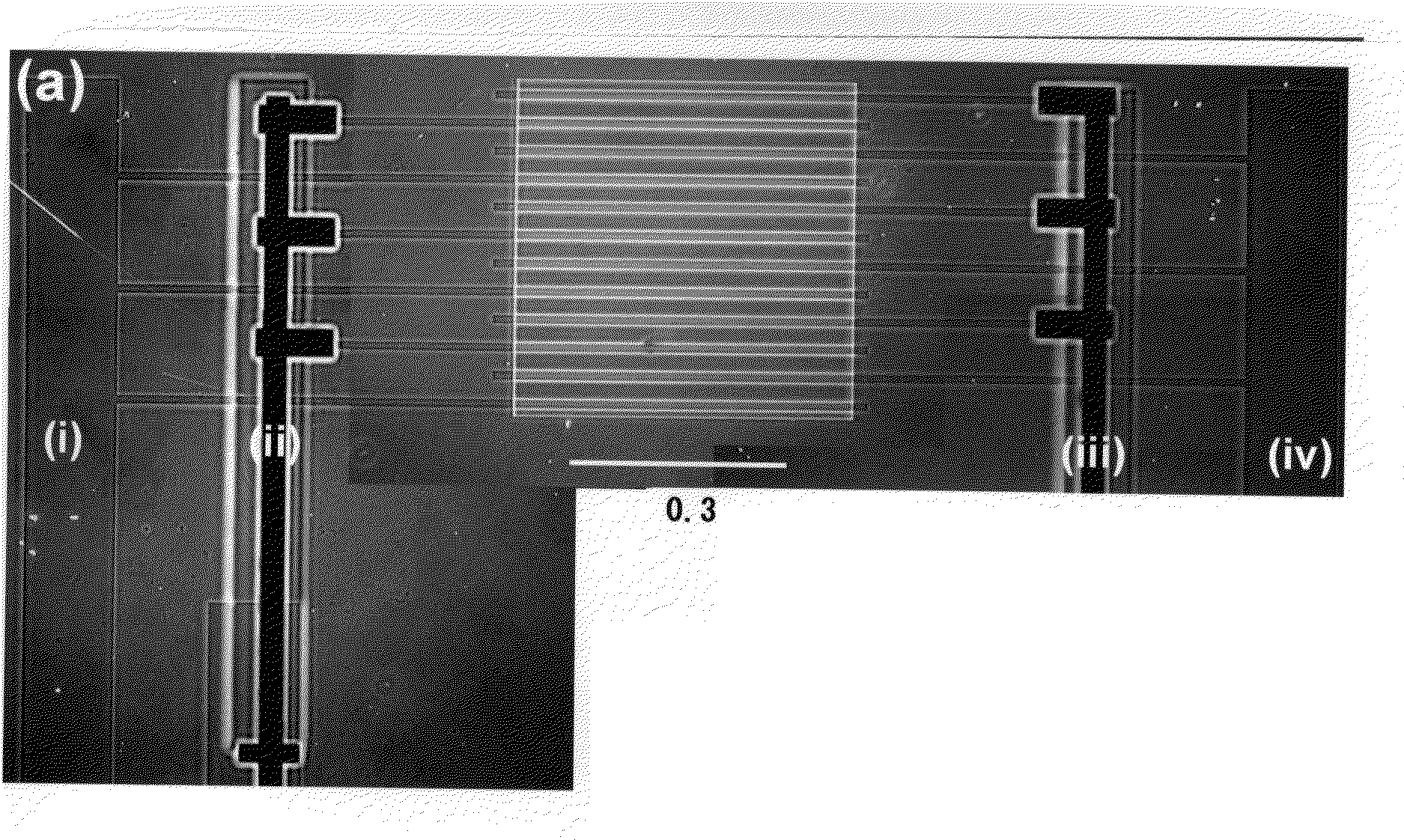
[0050]An electrode substrate was produced in which an IDA electrode with four independently-operating electrodes was formed by photolithography. FIG. 5 shows an outline view of the process of producing such an electrode substrate.

[0051]First, an ITO electrode substrate 10 (manufactured by Sanyo Vacuum Industries Co., Ltd.: 25 mm×35 mm) as shown in FIG. 5(a) was washed. Then the ITO electrode substrate 10 was spin-coated with hexamethyldisilasane, and a positive photoresist (manufactured by Shipley Company L. L. C under the trade name “S-1818”) in this order. Thereafter, the ITO electrode substrate 10 was baked for 3 minutes under a temperature condition of 110° C., subjected to UV irradiation (500 W, 10 seconds) through a photomask having a predetermined IDA electrode pattern. Then, the ITO electrode substrate 10 was immersed into a liquid developer (manufactured by Shipley Company L. L. C under the trade name “MICROPOSIT MF CD-26” to obtain an IDA e...

production example 2

Production of Cell Patterning Apparatus

[0061]An apparatus with a structure shown in FIG. 1 was produced. In such an apparatus, the electrode substrate (the IDA electrode with four independently-operating electrodes) produced in Production Example 1 was used as an electrode substrate 1. “TL-41MS-06K” manufactured by Lintec Corporation was used as a spacer 4. A culture slide (a polystyrene cell culture slide: 25×25 mm manufactured by Nalge Nunc International K.K.) was used as a cell culture substrate 3. The space between the electrode substrate 1 and the cell culture substrate 3 was set to 30 μm.

[0062]The electric field strength in such a cell patterning apparatus was calculated by use of finite element analysis software “COMSOL Multiphysics 3.1a (manufactured by Comsol, Inc. in Sweden). The calculation was conducted in a three dimensional model. The dimensions of the model was set to length (x axis) 900 μm×width (y axis) 10 μm×height (z axis) 30 μm. The electrode substrate was taken ...

production example 3

Culture of Cells (C2C12))

[0067]A mouse myoblast cell line (C2C12) was cultured. Specifically, the undifferentiated mouse myoblast cell line (C2C12) was cultured under conditions of 37° C., 5% by volume of CO2, and water vapor saturation in a Dulbecco's modified Eagle's minimal essential medium (DMEM: manufactured by Gibco) added with lot by volume of immobilized FBS (manufactured by Gibco), 25 U / mL of penicillin, and 25 μg / mL of streptomycin (manufactured by Gibco).


PUM


Abstract

Provided is a method for cell patterning, using an electrode substrate including a plurality of electrodes and a cell culture substrate disposed so as to face the electrode substrate, the method comprising the steps of:introducing a cell suspension containing cells into a region between the electrode substrate and the cell culture substrate; applying a voltage to the electrodes to generate a non-uniform electric field in the region; and arranging the cells at a position with low electric field strength on the cell culture substrate by utilizing negative dielectrophoresis so as to obtain the cell culture substrate on which the cells are arranged in a predetermined pattern.

Description

TECHNICAL FIELD[0001]The present invention relates to a method for cell patterning.BACKGROUND OF THE INVENTION[0002]It has been expected that techniques for performing in vitro reconstruction of an in vivo cellular environment are applied to various fields such as cell biological analysis of cell function, personalized drug screening by use of a cell array chip, elucidation of intercellular communication and cell-extracellular matrix communication for regenerative medicine. A technique for performing in vitro reconstruction of an in vivo cellular environment which has attracted attention is a cell patterning technique which is a technique for disposing cells, extracellular matrices, and cell adhesion molecules in any region at a micro-scale.[0003]For example, Japanese Unexamined Patent Application Publication No. Hei 2-245181 (Document 1) discloses a method for cell patterning utilizing an electrostatic charge pattern. In this method for cell patterning, a body tissue is attached on...

Claims


Application Information

Patent Timeline
IPC IPC(8): C12N13/00C12N5/07C12N5/071
CPCC12M33/00C12N2535/10C12N5/0068
Inventor YASUKAWA, TOMOYUKISUZUKI, MASATOSHIKU, HITOSHIHORI, YOSHIOINAGAKI, AKIKOKOMABAYASHI, MARIKOMATSUE, TOMOKAZU
Owner TOHOKU UNIV
Learn More