
Collimator

Active Publication Date: 2010-02-11
C-RAD INNOVATION AB
View PDF3 Cites 41 Cited by
  • Summary
  • Abstract
  • Description
  • Claims
  • Application Information

AI Technical Summary

Benefits of technology

[0007]It is a general object of the present invention to provide a light, compact and inexpensive collimator design.
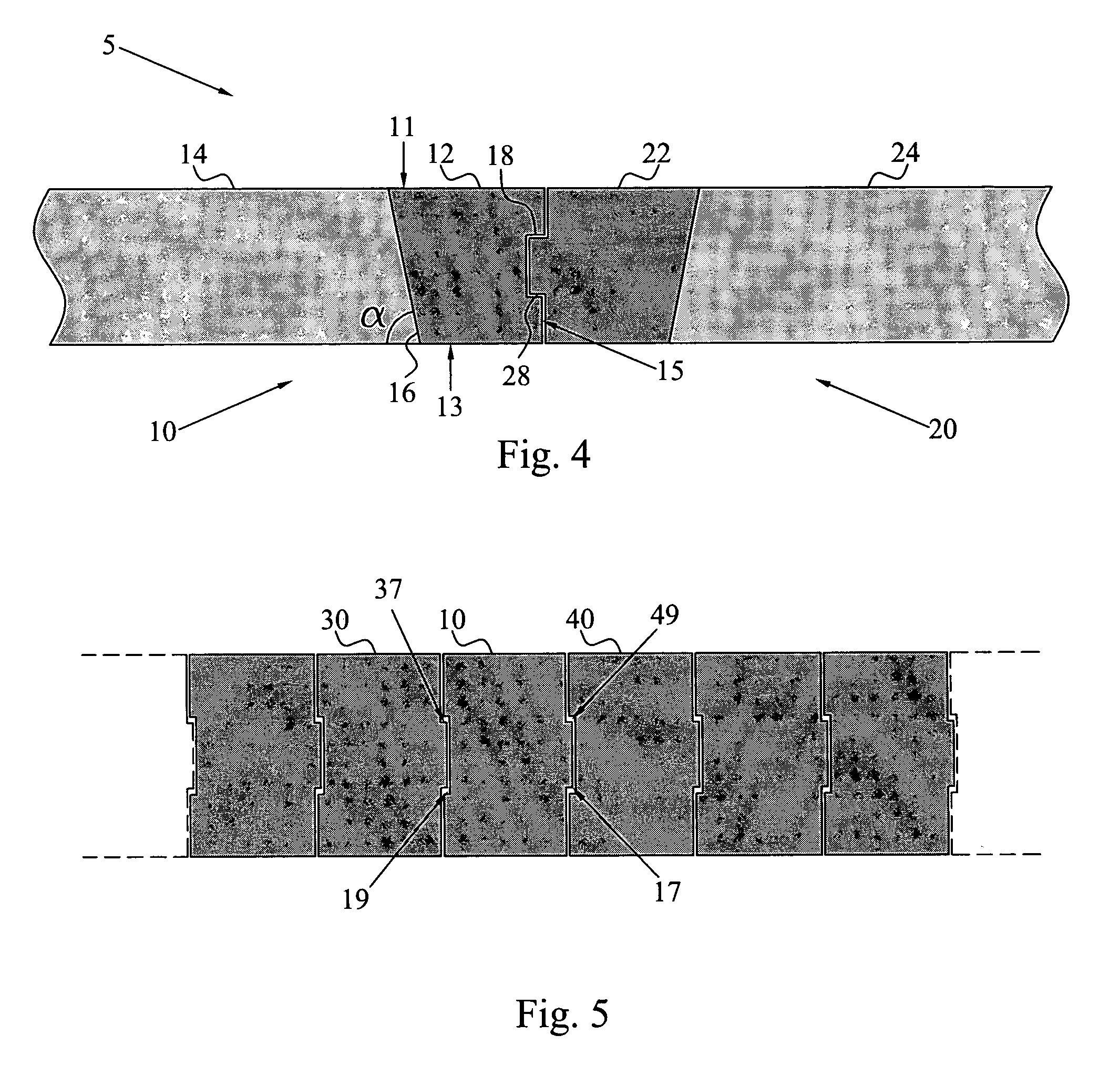
[0014]Preferred materials of the penumbra-trimming leaf portion includes high atomic number metals and metal alloys having a density of at least 15 g / cm3. The material of the support portion does not have the same radiation attenuating demands and is therefore, for reducing the weight, size and cost of the collimator, preferably made of a light metal or metal alloy materials.
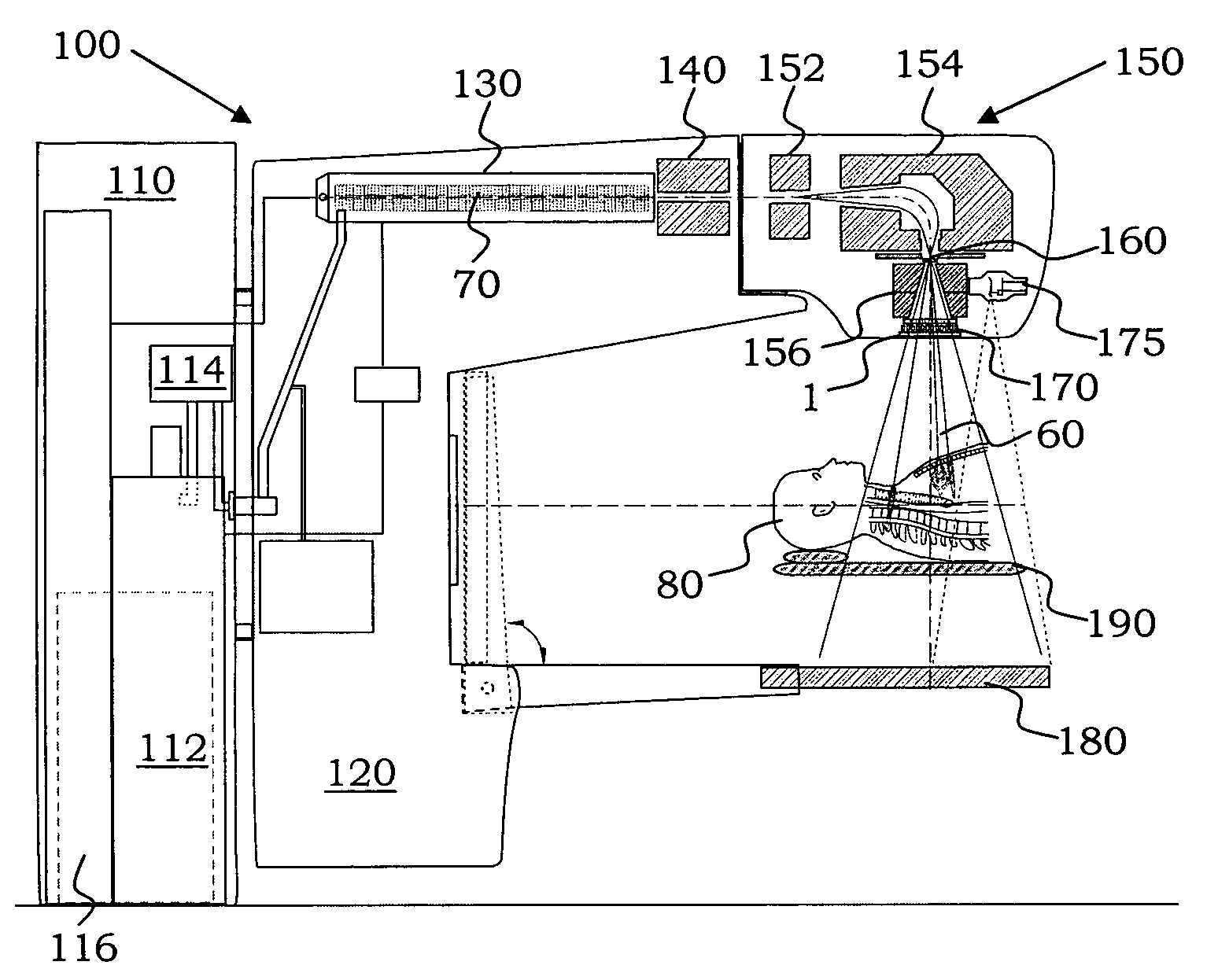
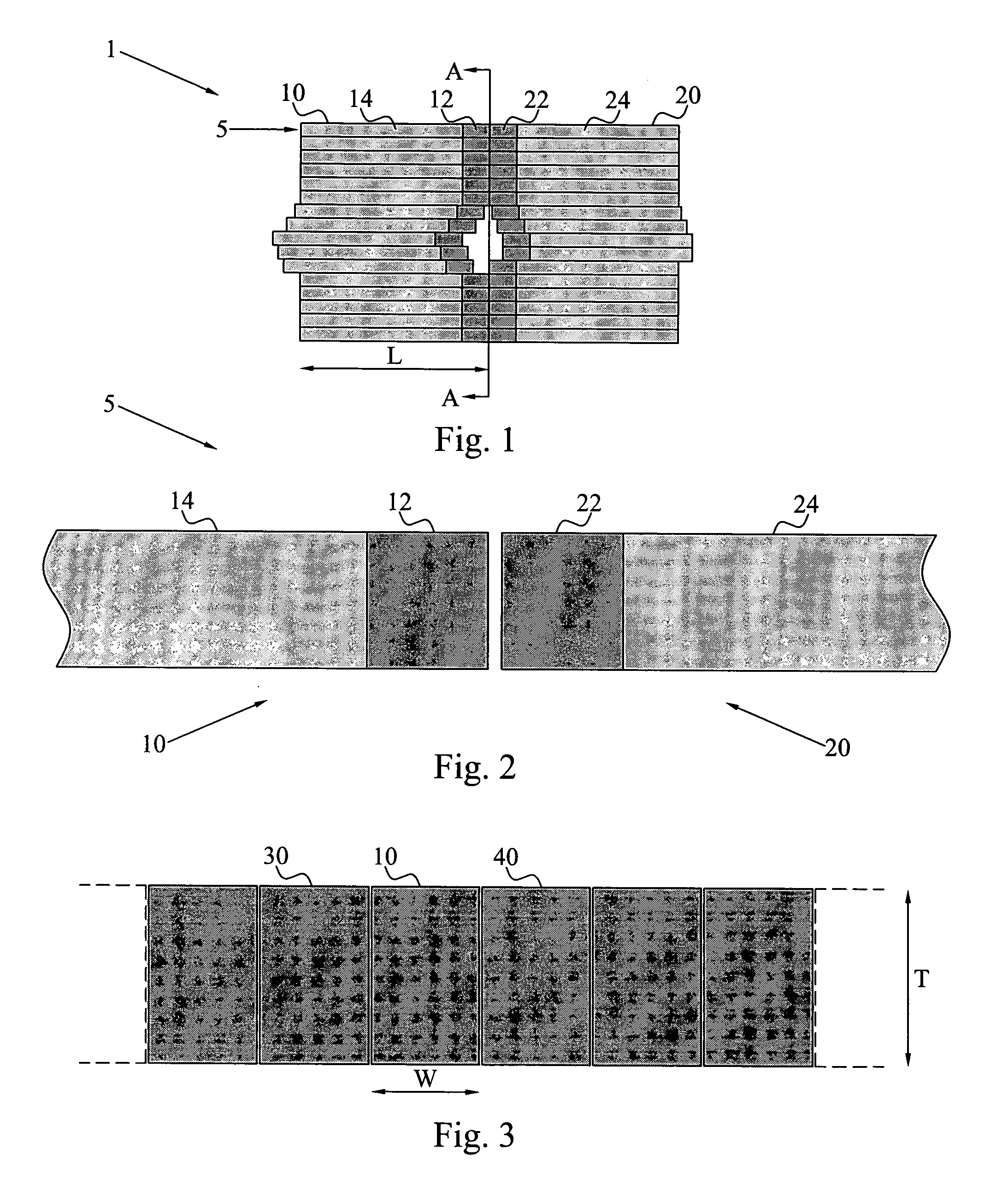
[0016]The fast low-weight collimator of the invention is capable of further sharpening the penumbra at the edge of the elementary scanned beam, in order to minimize the dose or radiation response of healthy tissues. In the case of photon beams, such a collimator can be placed relatively close to the bremsstrahlung target to minimize its size. It can also be flat and thin, e.g. only 15-25 mm thick in the direction of the beam with edges made of, for example, tungsten or preferably osmium to optimize the sharpening of the penumbra. The low height of the collimator will minimizes edge scatter from glancing incidence. The major portions of the collimator leafs can then be made of, for example, steel or even aluminum (or other light metals and alloys), so that the total weight of the collimator will be very low, such as about 10 kg, which may even allow high-speed collimation in real time in synchrony with organ movements.
[0021]The collimator can be manufactured at a low cost compared to the prior art collimators;
[0022]The collimator can easily be operated in due to low power needs; and

Problems solved by technology

The irradiation time using dynamic multileaf collimation depends strongly on the nature of the desired dose distribution, and it is difficult to reduce this time to less than the sum of the irradiation times for all individual peaks heights using dynamic leaf collimation.

Method used


Image

  • Collimator
  • Collimator
  • Collimator

Examples


Embodiment Construction

[0042]Throughout the drawings, the same reference characters will be used for corresponding or similar elements.

[0043]The present invention generally relates to a novel design of a collimator having significantly reduced weight, cost and overall size as compared to previously employed collimators. The collimator of the present invention is in particular adapted for usage in a radiation gantry using narrow scanned radiation beams, often denoted a pencil-beam scanning system in the art.

[0044]The collimator of the invention comprises at least one pair of collimator leaf. In most preferred embodiments, the collimator comprises multiple adjacent leaves and is therefore a so-called multileaf collimator. In the following, the collimator of the invention is mainly described embodied as a multileaf collimator unless mentioned otherwise. The invention, though, also encompasses single-pair collimators that comprise one pair of two opposite collimator leaves.

[0045]FIG. 1 is a schematic overview...


PUM


Abstract

A collimator (1) primarily adapted for usage in a narrow scanned pencil beam radiation therapy system (100) includes adjacent pairs (5) of collimator leaves (10, 20). An inner portion (12) of a collimator leaf (10) facing the opposite leaf (20) of a pair (5) is made of a first material having high linear radiation attenuation. The remaining, major portion (14) of the leaf (10) is made of a second material having a comparatively low density, weight and radiation attenuation. The collimator (1) provides effective penumbra trimming of a radiation beam (60), while simultaneously protecting healthy tissue around a tumor in an irradiated patient (80) from the radiation. The new design results in a significantly more compact, lighter and less expensive collimator (1) as compared to traditional collimators.

Description

TECHNICAL FIELD[0001]The present invention generally relates to a collimator, and in particular to a penumbra-trimming collimator useful in connection with scanning beam therapy and beam collimation.BACKGROUND[0002]Approximately half of the current young generation in the Western world will at some point in their lives be diagnosed as having cancer and this frequency is slowly increasing. More than half of these patients are likely to receive radiation therapy, due in particular to the increasing use and efficacy of intensity modulated radiation therapy (IMRT). Both the rising costs for cancer care and the adverse side-effects in normal tissues call for more locally effective treatment procedures such as radiation therapy, which is undoubtedly more cost-effective and generally more curative than both surgery or chemotherapy, and is being recommended more and more extensively. Extensive and mutilating surgery is now often replaced by minimally invasive surgery and will in the future ...

Claims


Application Information

Patent Timeline
IPC IPC(8): G21K1/04
CPCA61N5/1037A61N5/1042G21K1/046G21K1/04G02B27/30
Inventor SVESSON, ROGERBRAHME, ANDERS
Owner C-RAD INNOVATION AB
Learn More