Eureka AIR delivers breakthrough ideas for toughest innovation challenges, trusted by R&D personnel around the world.

Particulate matter detection device and method for manufacturing the same

a detection device and particle technology, applied in the direction of mechanical equipment, machines/engines, instruments, etc., can solve the problems of large error and increase cost, and achieve the effect of less error, small installation space, and inexpensive manufacturing

Inactive Publication Date: 2010-03-25
NGK INSULATORS LTD
View PDF3 Cites 9 Cited by
  • Summary
  • Abstract
  • Description
  • Claims
  • Application Information

AI Technical Summary

Benefits of technology

[0005]The present invention has been developed in view of the above problem, and an object thereof is to provide a particulate matter detection device which is small-sized, can minimize measurement errors and can inexpensively be manufactured.
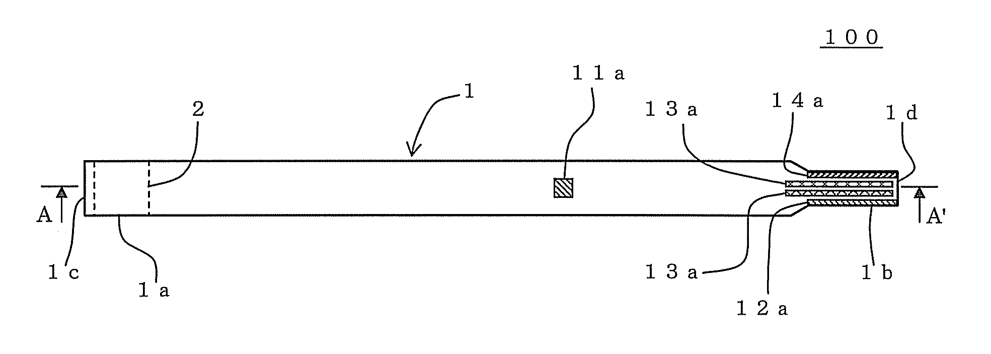
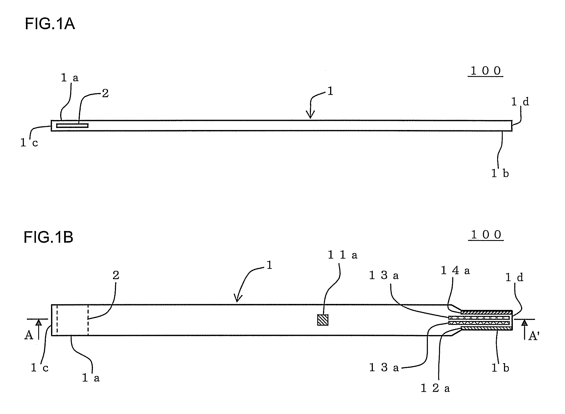
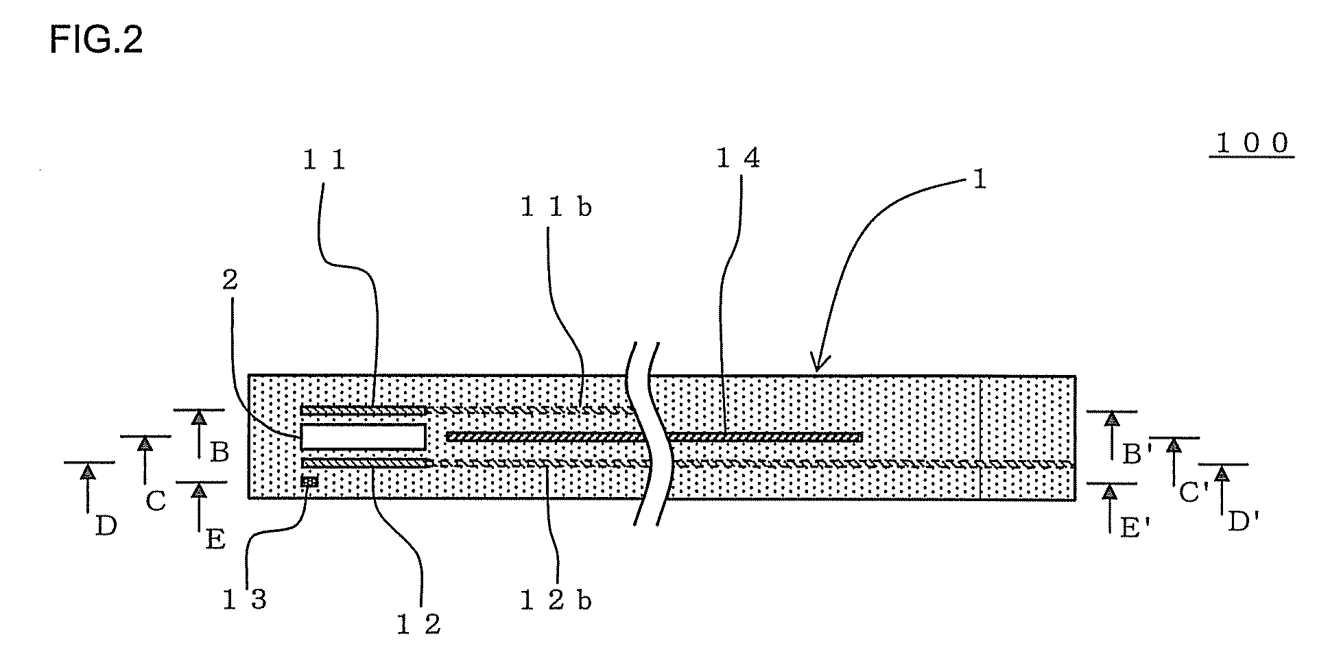
[0017]According to the particulate matter detection device of the present invention, at least the pair of electrodes are embedded in the wall of the detection device main body through which the through hole is formed, and the voltage is applied across the pair of electrodes to cause the electric discharge in the through hole, whereby the device can charge the particulate matter present in the through hole by the electric discharge, and can electrically adsorb the charged particulate matter by the electrodes. Therefore, in the exhaust gas flowing on the downstream side of a DPF, the mass of the particulate matter only of the exhaust gas which has flowed into the through hole can be measured. In consequence, all the particulate matter contained in the exhaust gas flowing on the downstream side of the DPF is not directly measured, but the mass of the only particulate matter flowing into the through hole can be measured to estimate the amount of the particulate matter contained in the whole exhaust gas. Consequently, the particulate matter detection device can be miniaturized, and can accordingly be installed in a small space. Furthermore, the device can inexpensively be manufactured. Moreover, even when the whole flow rate of the exhaust gas flowing on the downstream side of the DPF is high, an only part of the exhaust gas (the particulate matter) is introduced into the through hole, so that all the particulate matter in the through hole can effectively be charged, and a measured value with a less error can be obtained. Moreover, the detection device main body is formed so as to be prolonged in one direction, and has one end provided with the through hole in which at least the pair of electrodes are provided (embedded). Therefore, an only portion of the main body including the through hole and the pair of electrodes is inserted into a pipe through which the high-temperature exhaust gas circulates, and the other end of the main body can be protruded externally from the pipe. In consequence, portions such as the takeout terminals of the pair of electrodes which are preferably not exposed to the high temperature can be protruded externally from the pipe, and hence the particulate matter can accurately and stably be detected. Furthermore, the strip-like ground electrode is disposed at the position sandwiched between the wires extending from the pair of electrodes to the other end of the detection device main body, so that electric properties across the pair of electrodes can be detected while suppressing the influences of the wires extending from the pair of electrodes, respectively. In consequence, the changes of the electric properties of the wall through which the through hole is formed can accurately be measured.
[0018]Moreover, according to the present invention, the method for manufacturing the particulate matter detection device includes the steps of forming the forming material containing the ceramic material into the tape-like shape to prepare the plurality of green sheets which are prolonged in one direction; processing a part of the obtained plurality of green sheets into the predetermined green sheets provided with the electrodes, the predetermined green sheet provided with the ground electrode, and the predetermined green sheet provided with the cut portion; superimposing the plurality of green sheets on the two green sheets provided with the electrodes, respectively, to form the green sheets in which the electrodes are embedded in a state in which the electrodes and the wires are covered with the green sheets; laminating the green sheets so that the green sheet provided with the ground electrode and the green sheet provided with the cut portion are sandwiched between the two green sheets in which the electrodes are embedded, to form the green sheet laminate having the state in which the cut portion is sandwiched between the two electrodes and in which the ground electrode is sandwiched between the two wires; and drying and firing the green sheet laminate to obtain the particulate matter detection device. Therefore, the particulate matter detection device of the present invention can efficiently be obtained.

Problems solved by technology

Thus, in the method of charging the particulate matter to measure the ion current thereof, the ion current to charge the particulate matter is weak, and hence there is a problem that a large-scaled detection circuit is required for detecting the weak ion current, which increases cost.
Moreover, when an exhaust gas has a high flow rate, the particulate matter cannot effectively be charged, and hence there is a problem that the measured amount of the particulate matter is smaller than the amount of the particulate matter actually contained in the exhaust gas, which error is large.

Method used


Image

  • Particulate matter detection device and method for manufacturing the same
  • Particulate matter detection device and method for manufacturing the same
  • Particulate matter detection device and method for manufacturing the same

Examples


example 1

Preparation of Forming Material

[0087]Alumina was used as a dielectric material, polyvinyl butyral was used as a binder, di-2-ethyl hexyl phthalate was used as a plasticizer, sorbitan tri-oleate was used as a dispersant, and an organic solvent (xylene:butanol=6:4 (a mass ratio)) was used as a dispersion medium. These materials were placed into an alumina pot, and mixed to prepare a slurried forming material for the preparation of a green sheet. As the amounts of the used materials with respect to 100 parts by mass of alumina, 7 parts by mass of binder, 3.5 parts by mass of plasticizer, 1.5 parts by mass of dispersant, and 100 parts by mass of organic solvent were set.

[0088]Next, the obtained slurried forming material for the preparation of the green sheet was stirred under a reduced pressure, defoamed, and regulated to obtain a viscosity of 4 Pa·s. The viscosity of the slurry was measured by a B-type viscosity meter.

[0089](Forming Processing)

[0090]Next, the slurried forming material ...


PUM

PropertyMeasurementUnit
Fractionaaaaaaaaaa
Fractionaaaaaaaaaa
Temperatureaaaaaaaaaa

Abstract

A particulate matter detection device including a main body which has one end provided with a through hole; a pair of electrodes embedded in a wall through which the through hole is formed, and covered with a dielectric material; wires extending from the electrodes to the other end of the main body; and a ground electrode provided at a position sandwiched between the wires. The device can electrically adsorb, on the wall surface of the through hole, a charged particle in a fluid flowing into the through hole, or a particle charged by electric discharge caused in the through hole by applying a voltage across the pair of electrodes. The device can measure the changes of the electric properties of the wall through which the through hole is formed, thereby detecting particles adsorbed on the wall surface of the through hole.

Description

BACKGROUND OF THE INVENTION AND THE RELATED ART[0001]The present invention relates to a particulate matter detection device. More particularly, it relates to a particulate matter detection device which is small-sized, can minimize measurement errors and can inexpensively be manufactured.BACKGROUND ART[0002]A flue exhaust gas or a diesel engine exhaust gas includes a particulate matter (PM) such as soot, which has been a cause for air pollution. To remove the PM, a filter made of a ceramic material or the like (a diesel particulate filter: DPF) is broadly used. The ceramic DPF can be used for a long period of time, but a defect such as cracking or melting due to heat deterioration or the like occurs at times, and the PM might leak though a leak amount is small. When such a defect occurs, it is remarkably important from the viewpoint of the prevention of the air pollution to immediately detect the occurrence of the defect and to recognize the abnormality of a device.[0003]As a method ...

Claims


Application Information

Patent Timeline
IPC IPC(8): G01N37/00F01N11/00
CPCY10T29/49002G01N15/0656
Inventor SAKUMA, TAKESHIKONDO, ATSUOEGAMI, TAKASHI
Owner NGK INSULATORS LTD
Why Eureka
Eureka Blog
Learn More