
Electrochromic device and photodynamic treatment device comprising such an electrochromic device

a technology of electrochromic treatment and electrochromic device, which is applied in the field of electrochromic device, can solve the problems of limited application of known pdt devices and a single wavelength available for photodynamic therapy, and achieve the effect of maximizing and tuning the transmission, effective emission of a desired specific spectrum, and large lighting area

Inactive Publication Date: 2010-04-01
KONINKLIJKE PHILIPS ELECTRONICS NV
View PDF15 Cites 106 Cited by
  • Summary
  • Abstract
  • Description
  • Claims
  • Application Information

AI Technical Summary

Benefits of technology

[0005]In an embodiment of the electrochromic device according to the invention, the lighting device comprises multiple monochromatic light sources. Examples of monochromatic light sources are a laser and a light emitting diode (LED). According to this embodiment it is preferred to apply multiple LED's, which are preferably stacked on top of each other. In a preferred embodiment, the lighting device comprises at least one polychromatic light source. In this manner, the lighting device, and hence the electrochromic device can be manufactured relatively compactly. Although a conventional (polychromatic) light bulb could be used in the device according to the invention, it is more preferable to apply one or multiple polychromatic organic LED's (OLED's) or one or multiple polychromatic plastic or polymer LED's (PLED's), although the production costs of the PLED are rather expensive. Polychromatic LED's are significantly more compact than conventional light bulbs. With respect to a conventional solid-state LED, an OLED has the potential to be able to be produced much more cheaply. Moreover, OLED's are lighter than LED's, and can be produced relatively easily by means of known deposition techniques. A typical OLED comprises an anode, a cathode, and at least two organic material layers disposed between the anode and cathode. The anode in many OLED's comprises a relatively high work function material, such as indium tin oxide (ITO), and the cathode typically comprises a relatively low work function material, such as calcium (Ca). One of the organic material layers in a typical OLED comprises a material having the ability to transport holes, and is thus typically referred to as a hole transport layer. Another organic material layer typically comprises a material having the ability to transport electrons, and is thus typically referred to as an electron transport layer. The electron transport layer may also function as the luminescent medium (or emissive layer). Alternatively, an additional emissive layer may be disposed between the hole transport layer and the electron transport layer. In either case, when the OLED is properly biased, the anode injects holes (positive charge carriers) into the hole transport layer, and the cathode injects electrons into the electron transport layer. The injected holes and electrons each migrate toward the oppositely charged electrode. When an electron and hole localize on the same molecule, a Frenkel excitation is formed, and (visible) light is emitted.
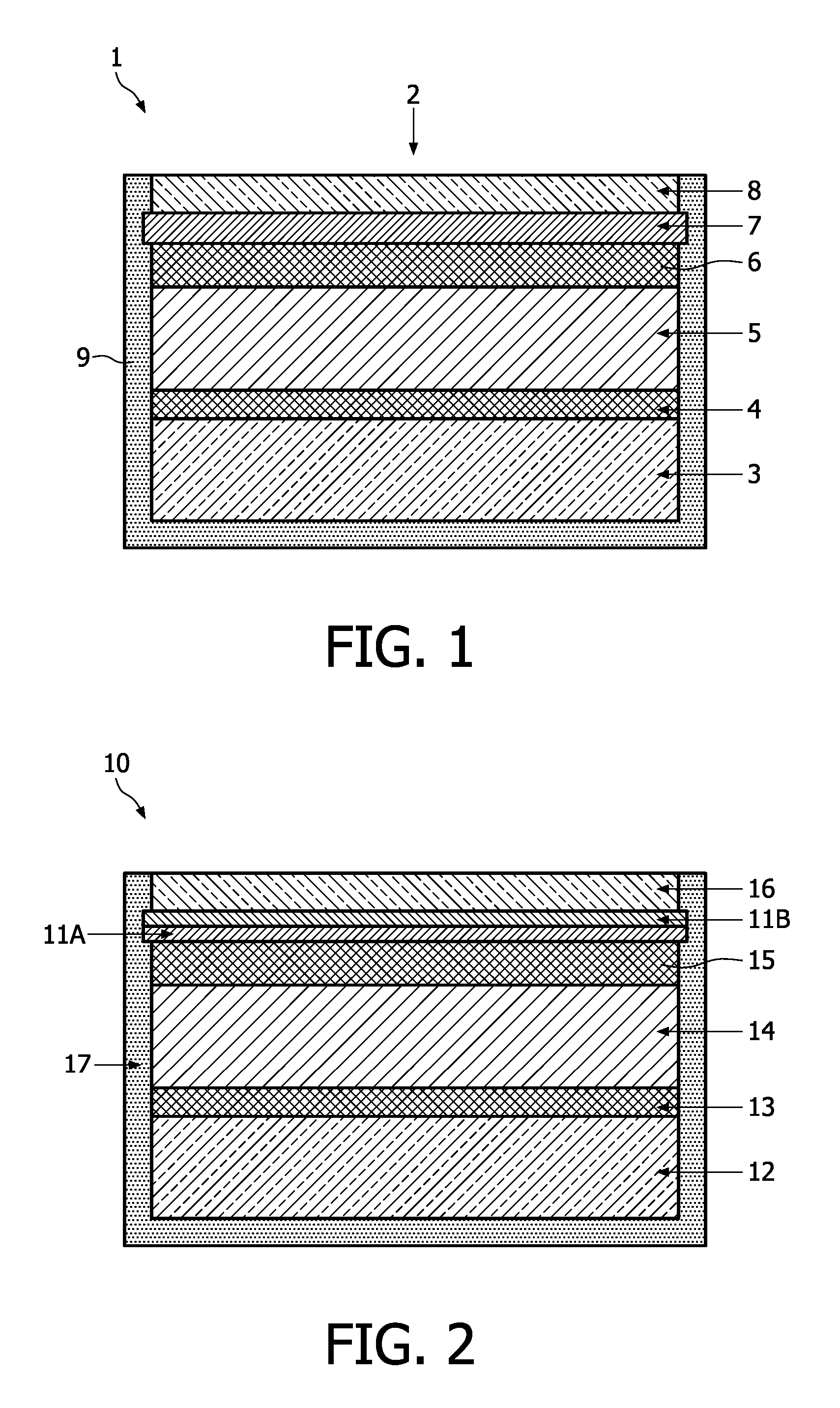
[0006]In a preferred embodiment the electrochromic device comprises multiple electrochromic windows. This embodiment may be advantageous in case a relatively large lighting area is desired or required, wherein the different electrochromic windows can be positioned adjacent to each other. In an alternative embodiment at least two electrochromic windows are adapted to exhibit different optical characteristics in response to a voltage applied to said windows. In accordance with this embodiment it could be advantageously to stack said mutually different electrochromic windows on top of each other. Since each electrochromic window can be switched on and off, and hence functions in fact as a switchable light filter, multiple switchable filters can be stacked on top of each other. This accumulative filtering may optimize and tune the transmission and hence the effective emission of a desired specific spectrum.
[0011]In a preferred embodiment the electrochromic device is partially surrounded by a packaging. The protective packaging is applied to prevent, or at least counteract, damaging of the electrochromic device. Since the packaging is commonly made of an opaque material, the electrochromic window is preferably left substantially uncovered by the packaging.
[0012]The invention also relates to a photodynamic treatment (PDT) device, comprising an electrochemical device according to the invention. To this end, the polychromatic lighting device is preferably chosen such that at least one photosensitizer can be activated by the wavelength(s) of the light emitted by said lighting device. In a preferred embodiment the PDT device is adapted for an in-vivo treatment of a human of animal body. More preferable, the PDT device is bioimplantable. In an alternative preferred embodiment the PDT is adapted for an ex-vivo treatment of a human or animal body. These (integrated or implantable) PDT devices can be advantageously used to for in-vivo or ex-vivo treatment of skin diseases, cancer / tumors, psoriasis, mood disorders, bladder infections, promoting wound closure, recovering spinal cord injuries, and countering muscle / bone atrophy.

Problems solved by technology

A major drawback of the known PDT device is that merely a single wavelength is available for photodynamic therapy.
Since particular (biological) processes require certain (merely) specific wavelengths, the application of the known PDT devices is limited to the activation of photosensitizers falling within the wavelength range emitted by the PDT device.

Method used


Image

  • Electrochromic device and photodynamic treatment device comprising such an electrochromic device
  • Electrochromic device and photodynamic treatment device comprising such an electrochromic device
  • Electrochromic device and photodynamic treatment device comprising such an electrochromic device

Examples


Embodiment Construction

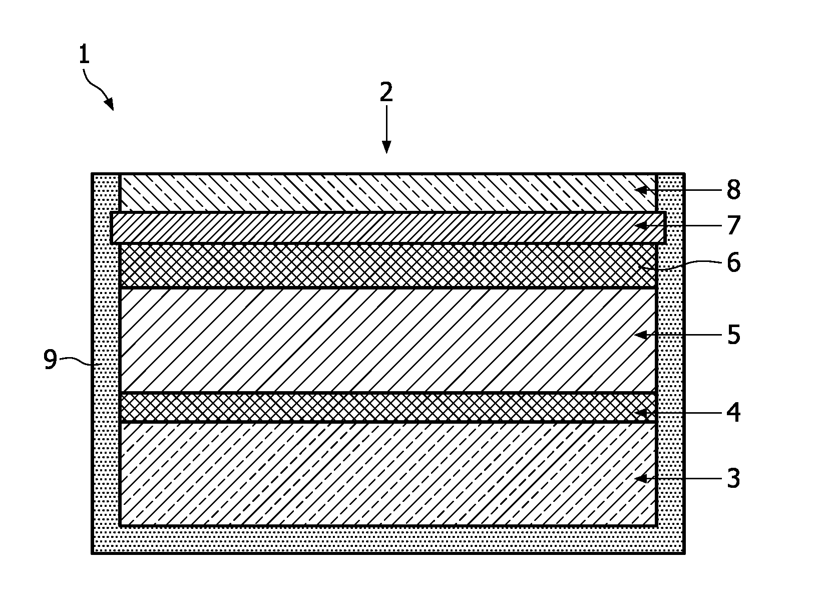
[0018]FIG. 1 shows a schematic cross section of an electrochromic device 1 according to the invention. The electrochromic device 1 shown in FIG. 1 is adapted to be used as a photodynamic treatment (PDT) device. The electrochromic device 1 comprises a laminate 2 of a thin-film solid-state battery 3 deposited onto a substrate (not explicitly shown), on top which battery 3 a first separation layer 4, a control unit 5, a second separation layer 6, a polychromatic OLED 7, and a electrochromic window 8 have been deposited successively. The integrated battery 3 is adapted for powering both the polychromatic OLED 7 and electrochromic window 8. The electrochromic window 8 is switchable by means of the control unit 5, and hence can be switched on and off. The electrochromic window 8 is switchable at least between a substantially transparent state and a state in which the window 8 is at least partially opaque. In this manner, the electrochromic window 8 will function in fact as a regulable lig...


PUM

PropertyMeasurementUnit
wavelength rangeaaaaaaaaaa

Abstract

Presently, many variations of light treatment are used in health care. Prime examples are the in-vivo or ex-vivo photodynamic treatment (PDT) of skin diseases, cancer / tumors, psoriasis, mood disorders, bladder infections, promoting wound closure, recovering spinal cord injuries, and countering muscle / bone atrophy. PDT is a treatment that uses a drug, called a photo-sensitizer or photosensitizing agent, and a particular type of light. The invention relates to an improved PDT device.

Description

FIELD OF THE INVENTION[0001]The invention relates to an electrochromic device. The invention also relates to a photodynamic treatment device, comprising such an electrochromic device.BACKGROUND OF THE INVENTION[0002]Presently, many variations of light treatment are used in health care. Prime examples are the in-vivo or ex-vivo photodynamic treatment (PDT) of skin diseases, cancer / tumors, psoriasis, mood disorders, bladder infections, promoting wound closure, recovering spinal cord injuries, and countering muscle / bone atrophy. PDT is a treatment that uses a drug, called a photosensitizer or photosensitizing agent, and a particular type of light. When photosensitizers are exposed to a specific wavelength of light, they produce reactants, like oxygen radicals, that kills nearby cells. Each photosensitizer is activated by light of a specific wavelength. As this wavelength determines how far the light can travel into the body, specific photosensitizers and wavelengths of light are utiliz...

Claims


Application Information

Patent Timeline
Patent Type & Authority Applications(United States)
IPC IPC(8): A61N5/06G02F1/153
CPCA61N5/0601A61N5/062G02F1/157A61N2005/0653A61N2005/0667A61N2005/0651
Inventor NIESSEN, ROGIER ADRIANUS HENRICANOTTEN, PETRUS HENRICUS LAURENTIUSPIJNENBURG, REMCO HENRICUS WILHEMUS
Owner KONINKLIJKE PHILIPS ELECTRONICS NV
Learn More