

Multifunctional radiation-hardened laminate
- Summary
- Abstract
- Description
- Claims
- Application Information
AI Technical Summary
Benefits of technology
Problems solved by technology
Method used
Image

Examples
first embodiment
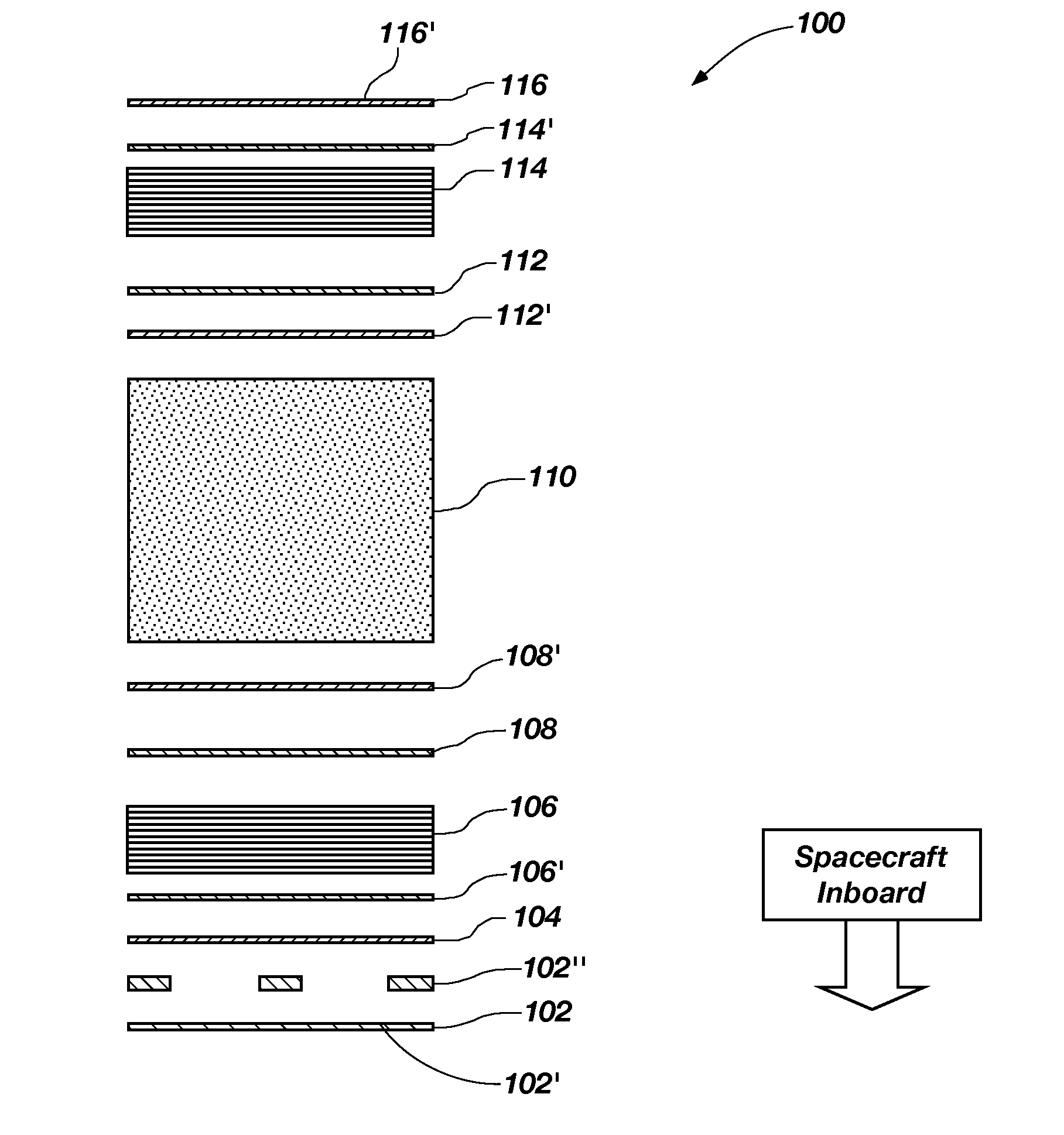
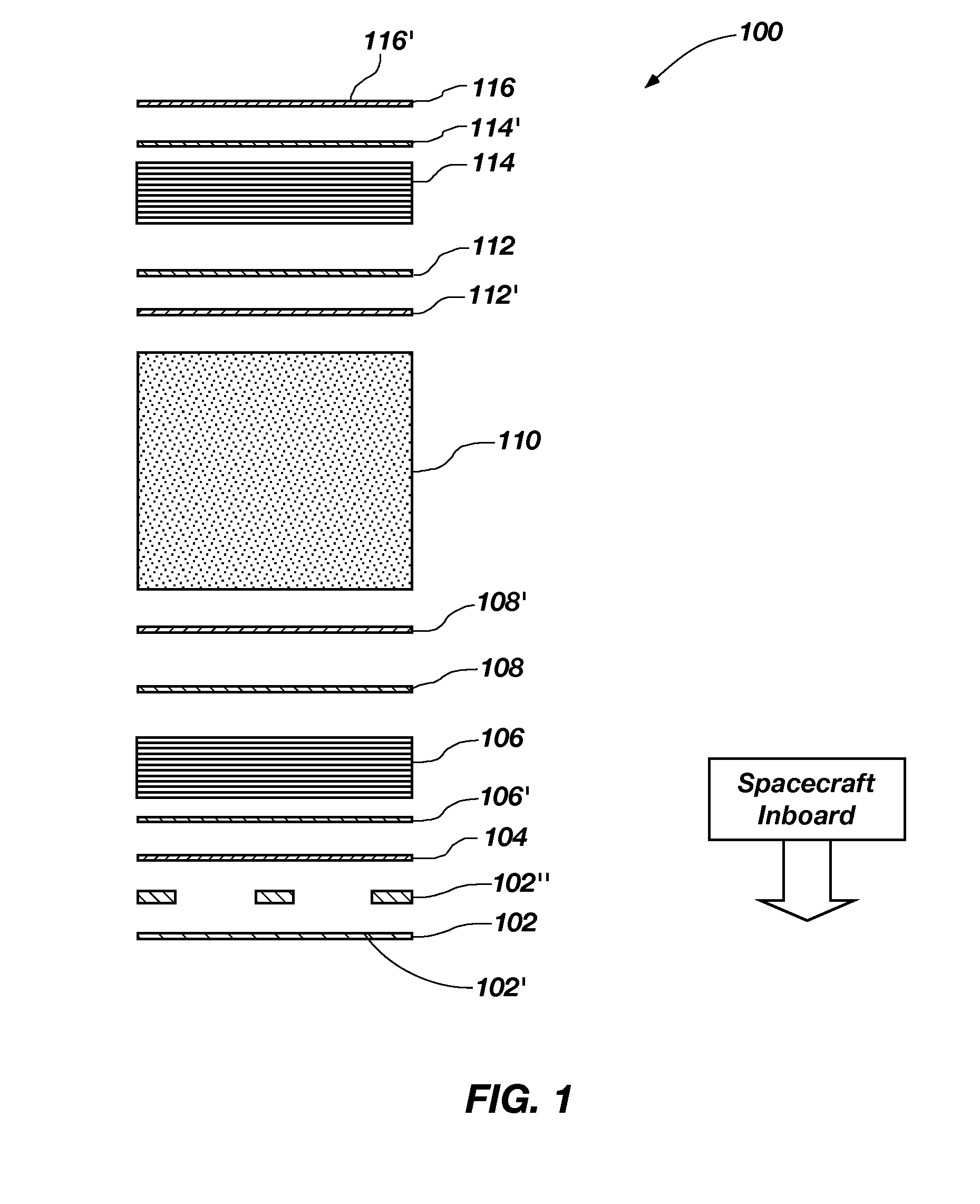
[0020]Referring to drawing FIG. 1, the composite structure 100 of the invention for use in forming flat cored panels which are radiation resistant, have high strength to weight, low distortion, and have high rigidity is illustrated in cross-section. The composite structure 100 comprises a laminate including various layers of materials. From the inboard of the space craft, a layer 102 of high density polyethylene optionally hydrogenated with carbon nano-tubes may be used with the layer 102 or having a metallized layer of aluminum 102′ thereon. The thickness of the layer 102 of the high density polyethylene film or fabric and the thickness of the metallized layer of aluminum 102′ thereon may be any desired thickness to be determined by the environment, the loading, and the particular application in which the composite is to be used and is attached by thin epoxy layer 102″.
[0021]Located outboard of the layer 102 is a layer 104 of metallic foil; preferring one or more layers of tantalum...
second embodiment
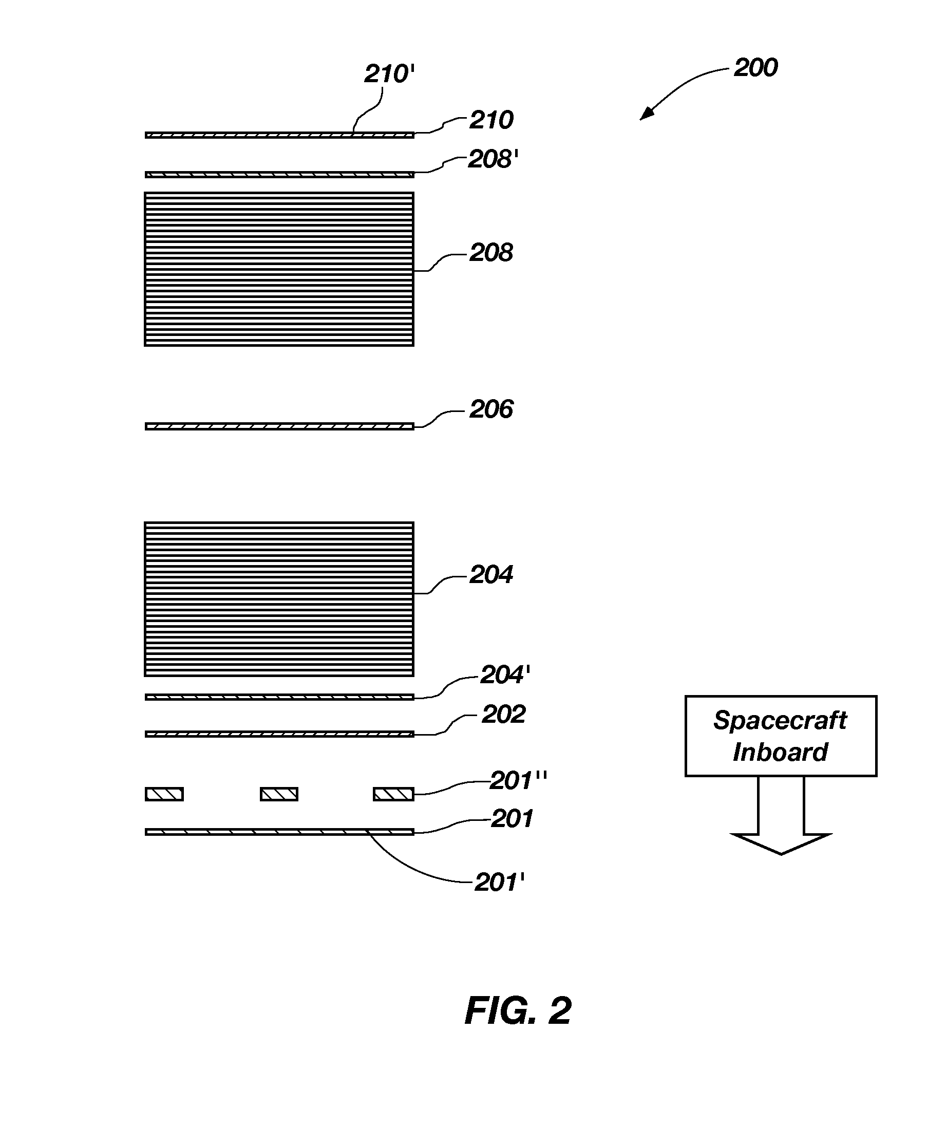
[0036]Referring to drawing FIG. 2, the composite structure 200 of the invention for use in forming an enclosed cylindrical or rhomboid tube shaped laminates which are radiation resistant, have high strength to weight, and have high rigidity is illustrated in cross-section. The composite structure 200 comprises a laminate including various layers of materials. From the inboard of the enclosed part, a layer 201 of high density polyethylene film or fiber fabric may be used with the layer 201 optionally being hydrogenated with carbon nano-tubes or having a metallized layer 201′ thereon. The thickness of the layer 201 of the high density polyethylene film or fiber fabric and the thickness of the metallized layer 201′ thereon may be any desired thickness to be determined by the environment, the loading, and the particular application in which the composite is to be used and is attached by a thin epoxy layer 201″.
[0037]Located outboard of the layer 201 is layer 202 of metallic foil; prefer...
third embodiment
[0047]Referring to drawing FIG. 3, the composite structure 300 of the invention for use in forming layered flat boron separated laminate panels which are radiation resistant, have high strength to weight, and have high rigidity is illustrated in cross-section. The composite structure 300 comprises a laminate including various layers of materials. From the inboard of the space craft, a layer 302 of high density polyethylene film or fiber fabric may be used with the layer 302 optionally being hydrogenated with carbon nano-tubes or having a metallized layer 302′ thereon. The thickness of the layer 302 of the high density polyethylene film or fiber fabric and the thickness of the metallized layer thereon may be any desired thickness to be determined by the environment, the loading, and the particular application in which the composite is too used and is attached by a thin epoxy layer 302″.
[0048]Located outward of the layer 302 is a layer 304 of metallic foil; preferring one or more laye...
PUM
| Property | Measurement | Unit |
|---|---|---|
| Percent by volume | aaaaa | aaaaa |
| Weight | aaaaa | aaaaa |
| Structure | aaaaa | aaaaa |
Abstract
Description
Claims
Application Information