
Method for preparing metal oxide sol, method for preparing metal oxide thin film using said sol, and solid oxide fuel cell comprising said thin film

Inactive Publication Date: 2010-04-15
KOREA INST OF SCI & TECH
View PDF3 Cites 13 Cited by
  • Summary
  • Abstract
  • Description
  • Claims
  • Application Information

AI Technical Summary

Benefits of technology

[0008]Accordingly, it is an object of the present invention to provide a method for preparing a metal oxide thin film on a porous substrate, using a sol-gel process by which a microstructure that is stable at a low-temperature process can be easily prepared.
[0014]According to the present invention, when a metal oxide thin film is formed on a porous substrate using a sol-gel process, the resulting microstructure can be easily controlled without using high-cost equipments and starting materials, the shape and size of the substrate does not become a limiting factor, and a phase that is stable at a low SOFC operating temperature can be easily acquired. The metal oxide film formed in this way is dense to such a degree that it is impermeable to gases, is resistant to the generation of cracks or pinholes, and exhibits a low electrical resistance because of its thin structure, and it is stable and durable when used in a low-temperature SOFC process. Therefore, the inventive metal oxide film can be beneficially used as an electrolyte for a fuel cell or an oxygen sensor, and it can also be applied to thermal barrier coating, optical materials, high-temperature superconductive thin buffer layers, insulation films in the fields of electronic devices, and others.

Problems solved by technology

For this reason, there exists the problem that the materials for SOFC components are limited because of high production costs and gradual performance degradation under such a high temperature condition.
However, such gas-phase processes are problematic in that the use of high-cost equipments and starting materials is required, the shape and size of the substrate are limited, the formation of a film is slow, and it is difficult to form a pinhole-free film.
However, when the thickness of the electrolyte thin film is smaller than the particle size of the powder, the electrolyte thin film disintegrates during grain growth, which makes it difficult to form a dense thin film.

Method used


Image

  • Method for preparing metal oxide sol, method for preparing metal oxide thin film using said sol, and solid oxide fuel cell comprising said thin film
  • Method for preparing metal oxide sol, method for preparing metal oxide thin film using said sol, and solid oxide fuel cell comprising said thin film
  • Method for preparing metal oxide sol, method for preparing metal oxide thin film using said sol, and solid oxide fuel cell comprising said thin film

Examples


example 1

Preparation of YSZ Thin Film Structure (1)

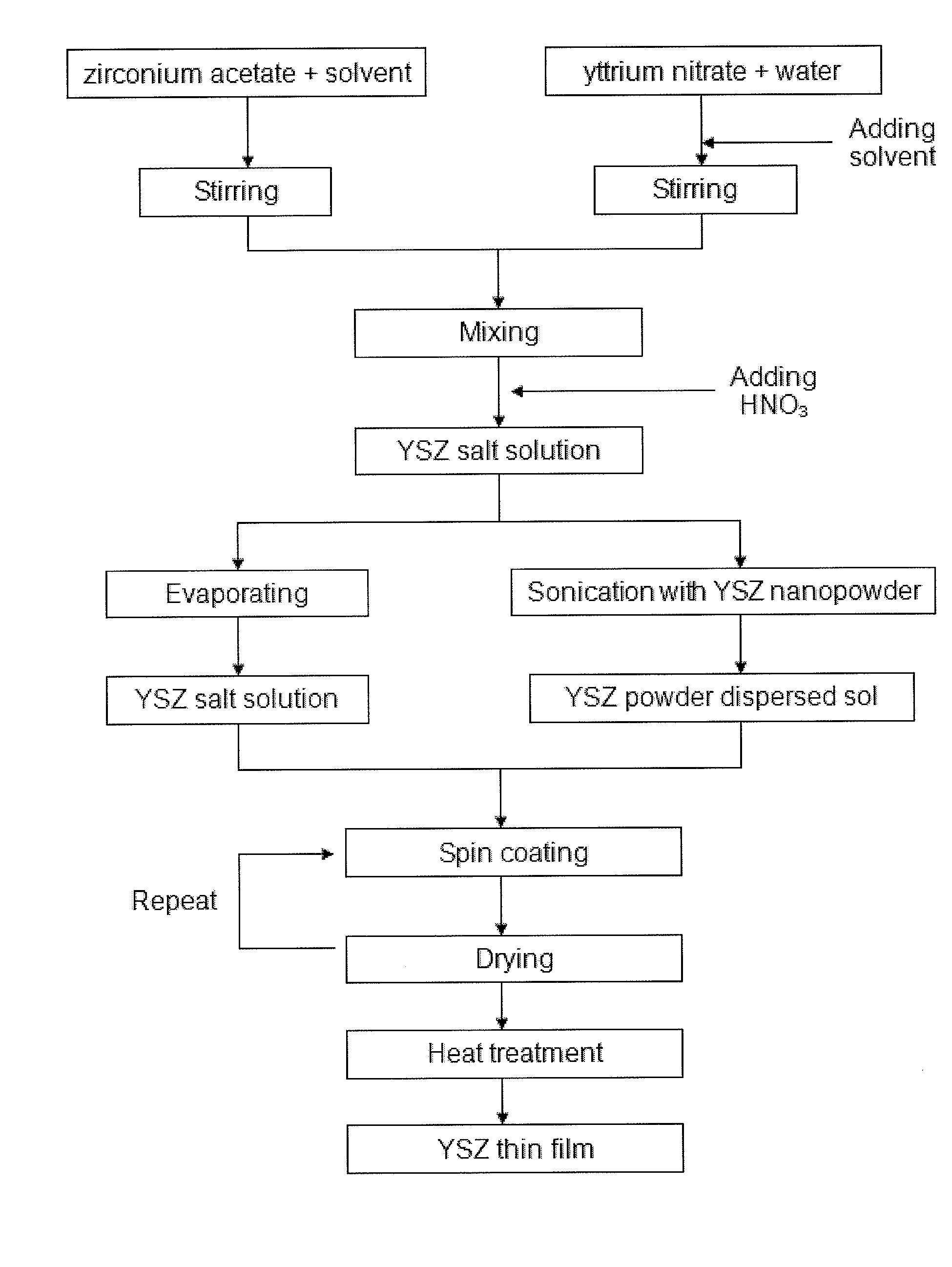
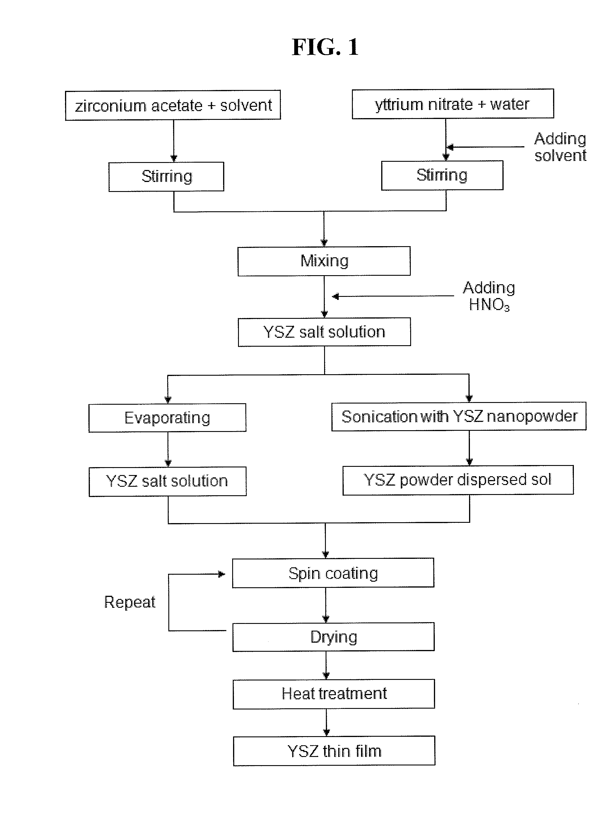
[0046]A YSZ thin film structure was prepared by following procedures, which are schematically shown in FIG. 1.

1-1. Preparation of YSZ Powder Dispersed Sol and YSZ Salt Solution

[0047]a) Ethanol as a solvent, DMF (C3H7NO) as a solvent and drying adjuster, and acetylacetonate (C5H8O2) as a chelating agent were mixed at a volume ratio of 30:40:30 (%), and then stirred at room temperature for 30 min to form a dispersion solution.

[0048]b) 82.6 g of the dispersion solution was added to 53.21 g of zirconium acetate in dilute acetic acid, then stirred for 1 hour, thus obtaining a first salt solution. Another 82.6 g of the dispersion solution was added to 16.5 g of yttrium nitrate hexahydrate (Y(NO3)3.6H2O), then stirred for 30 min, thus obtaining a second salt solution. The first and the second salt solutions were mixed together and stirred at room temperature for 2 hours, then nitric acid (HNO3) as a catalyst was added to obtain a YSZ salt solution ...

example 2

Preparation of YSZ Thin Film Structure (2)

2-1. Preparation of YSZ Powder Dispersed Sols

[0060]3.3 g of yttrium nitrate hexahydrate (Y(NO3)3.6H2O) and 20.49 g of zirconyl (IV) chloride octahydrate (ZrOCl2.8H2O) were dissolved in a mixed solvent in which diethyleneglycol monobutyl ether, ethanol and water were mixed at a volume ratio of 40:40:20 (%), and then 20 wt % of acetyl acetone as a chelating agent was added thereto, so as to obtain a first salt solution.

[0061]1 wt % of YSZ nanopowder (particle size: 20-30 nm, specific surface area: 160 m2 / g, available from fuelcellmaterials.com) was dispersed in a mixed solvent in which diethyleneglycol monobutyl ether, ethanol and water were mixed at a volume ratio of 40:40:20 (%), and irradiated with ultrasonic waves (60% power) to obtain a second salt solution.

[0062]The first and the second salt solutions were mixed at a volume ratio of 50:50 to obtain a YSZ powder dispersed sol.

2-2. Preparation of YSZ Thin Film Structure

[0063]The YSZ powder...

example 3

Preparation of SOFC Unit Cell

3-1. Preparation of YSZ Thin Film Structures

[0066]A first structure, in which a YSZ thin film having a thickness of 1 μm is formed on the substrate, was prepared in the same manner as in Example 1, with exception that the spin-coating was conducted as following steps:

[0067]i) spin-coating once with the 10 wt % YSZ powder dispersed sol;

[0068]ii) spin-coating once with the 5 wt % YSZ powder dispersed sol;

[0069]iii) spin-coating twice with the YSZ salt solution (2 mol / L); and

[0070]iv) spin-coating twice with the YSZ salt solution (1 mol / L).

[0071]In the first structure, the thickness of the YSZ salt solution layer formed in steps iii) and iv) was in a range of 50 to 400 nm.

[0072]Further, a second structure, in which a YSZ thin film having a thickness of 0.5 μm is formed on the substrate, was prepared in the same manner as in Example 1, with exception that the spin-coating was conducted as following steps:

[0073]i) spin-coating once with the 5 wt % YSZ powder ...


PUM

PropertyMeasurementUnit
Temperatureaaaaaaaaaa
Thicknessaaaaaaaaaa
Particle sizeaaaaaaaaaa

Abstract

A metal oxide thin film structure for a solid oxide fuel cell, prepared by a method comprising dispersing a metal oxide nanopowder in a metal oxide salt solution and subsequent coating of the resulting metal oxide powder dispersed sol and the metal oxide salt solution on a porous substrate, has excellent gas impermeability, excellent phase stability, and is devoid of cracks or pinholes.

Description

FIELD OF THE INVENTION[0001]The present invention relates to a method for manufacturing a metal oxide thin film structure using a sol-gel process, and to a solid oxide fuel cell (SOFC) comprising the metal oxide thin film.BACKGROUND OF THE INVENTION[0002]A solid oxide fuel cell (SOFC) comprises an air electrode (cathode), a fuel electrode (anode) and an electrolyte, wherein the electrolyte is the most important component which influences the performance of the SOFC.[0003]The electrolyte used in an SOFC is sintered at a high temperature of 1000 to 1400° C. so as to form a dense microstructure that prevents the mixing of oxygen and fuel. An SOFC is generally operated at a high temperature of 800° C. or more to maintain the oxygen ion conductivity at a high level. For this reason, there exists the problem that the materials for SOFC components are limited because of high production costs and gradual performance degradation under such a high temperature condition.[0004]Recently, there h...

Claims


Application Information

Patent Timeline
IPC IPC(8): H01M8/10B05D5/12B05D1/04C09D1/00
CPCC09D1/00H01M8/1253Y02E60/525Y02E60/521H01M2008/1293Y02E60/50Y02P70/50H01M4/86H01M8/04H01M8/10
Inventor LEE, HAE-WEONLEE, JONG HOOH, EUN OAKSON, JI-WONKIM, HAE-RYOUNGKIM, HYOUNGCHULLEE, KYUNG-RYUL
Owner KOREA INST OF SCI & TECH
Learn More