Radioactive fluorine anion concentrating device and method

a technology of fluoride anion and concentrating device, which is applied in the field of radioactive fluoride anion concentrating device, to achieve the effects of reducing the volume of an obtained organic solvent solution, and increasing the specific surface area

Inactive Publication Date: 2010-04-29
SHIMADZU CORP +1
View PDF7 Cites 8 Cited by
  • Summary
  • Abstract
  • Description
  • Claims
  • Application Information

AI Technical Summary

Benefits of technology

[0024]According to the present invention, the distance between the electrodes constituting the flow cell is 500 μm or less, and therefore, a potential gradient between the electrodes is large even when a voltage applied between the electrodes is low so that a large force acts on 18F− ions. Further, by providing a space having a volume of several hundred microliters or less as the flow channel of the flow cell, it is possible to increase the specific surface area of the glassy carbon electrode per unit volume of the flow channel. Therefore, the radioactive fluoride anion concentrating ...

Problems solved by technology

Further, [18O]H2O as a raw material of 18F− ions is expensive, and therefor...

Method used


Image

  • Radioactive fluorine anion concentrating device and method
  • Radioactive fluorine anion concentrating device and method
  • Radioactive fluorine anion concentrating device and method

Examples


first embodiment

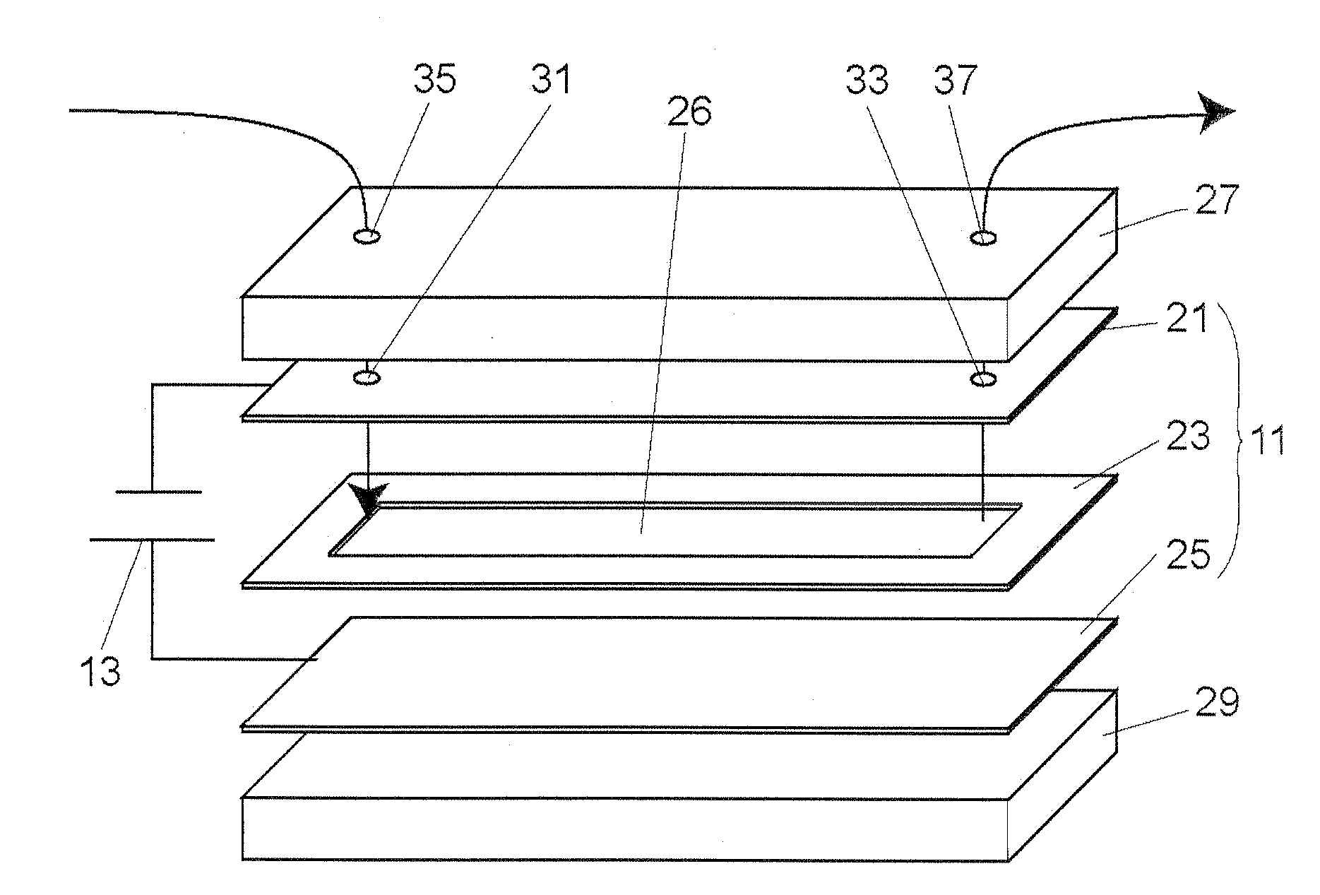
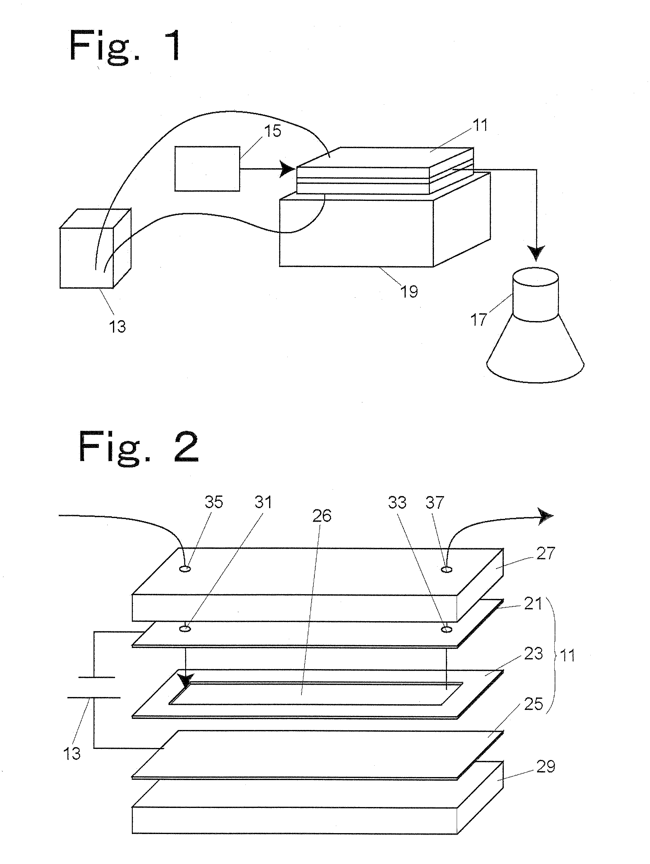
[0059](1) A solution containing 18F− ions is introduced into the flow cell 11 through the sample inlet 31.

[0060](2) The power source 13 applies a voltage between the metal plate electrode 21 and the glassy carbon electrode 25 to allow the glassy carbon electrode 25 to capture 18F− ions.

[0061](3) The solution contained in the flow channel 26 is discharged from the flow cell 11 through the sample output 33.

[0062](4) The flow cell 11 is filled with acetonitrile containing an agent for recovering 18F− ions, and then the polarity of the voltage applied to the glassy carbon electrode 25 is reversed to recover the 18F− ions captured by the glassy carbon electrode 25 using the acetonitrile.

[0063](5) The acetonitrile containing 18F− ions is discharged from the flow cell 11 through the sample outlet 33.

[0064](6) The flow cell 11 is filled with acetonitrile introduced through the sample inlet 31 to clean the inside of the flow cell 11.

[0065](7) The cleaning fluid (acetonitrile) is discharged f...

second embodiment

[0086]The radioactive fluoride anion concentrating device according to a second embodiment of the present invention has the same structure as the first embodiment shown in FIGS. 1 and 2, but the carbon plate electrode of the flow cell 11 is a graphite electrode 25.

[0087]The flow cell 11 has the metal plate electrode 21, the insulating sheet 23, and the graphite electrode 25. In the flow cell 11, the metal plate electrode 21 and the graphite electrode 25 are arranged so that the electrode sides thereof are opposed to each other, and the insulating sheet 23 is sandwiched between the metal plate electrode 21 and the graphite electrode 25.

[0088]It is to be noted that in the flow cell 11 shown in FIG. 2, one of the electrodes is a graphite electrode and the other electrode is a metal plate electrode, but one of the electrodes may be a glassy carbon electrode and the other electrode may be a carbon electrode, or both of the electrodes may be carbon electrodes.

[0089]Hereinafter, the proced...


PUM

PropertyMeasurementUnit
Lengthaaaaaaaaaa
Thicknessaaaaaaaaaa
Thicknessaaaaaaaaaa

Abstract

A radioactive fluoride anion concentrating device capable of concentrating 18F ions speedily and efficiently. A flow cell (11) is composed of a metal plate electrode (21), an insulating sheet (23) and a carbon plate electrode (25) located so that the sides of electrodes may be opposed to each other with the insulating sheet (23) inserted between them. An example of the plate metal plate electrode (21) is obtained by forming a film of metallic material on an insulation plate, and an example of the insulating sheet (23) is a PDMS from which a groove being a channel (26) having a thickness of ≦500 μm is cut out. The thickness of the sheet is desirably about 100 μm. The upper and lower sides of the flow cell (11) are fixed by fixing jigs (27) and (29).

Description

TECHNICAL FIELD[0001]The present invention relates to a radioactive fluoride anion concentrating device by which 18F− ions obtained by irradiating [18O]H2O with protons accelerated by a cyclotron are separated from the [18O]H2O to produce an organic solvent solution containing the 18F− ions.BACKGROUND ART[0002]PET (Positron Emission Tomography) is one of the medical diagnostic techniques using radioactive tracer compounds, but most of the radioactive nuclides used in PET have relatively short half-lives. For example, the half-life of 18F− is about 110 minutes. Therefore, it is necessary to efficiently introduce such a radioactive nuclide into a tracer compound in a short period of time to radioactivate the tracer compound.[0003]Further, [18O]H2O as a raw material of 18F− ions is expensive, and therefore, there is a demand for reuse of [18O]H2O to reduce the cost of diagnosis by PET.[0004]A radioactive tracer compound used in, for example, PET has a time limit due to a short lifetime...

Claims


Application Information

Patent Timeline
IPC IPC(8): G21G4/08
CPCC01B7/20G21G2001/0015G21G1/001
Inventor IWATA, RENOZEKI, EIICHINAKANISHI, HIROAKISAKAMOTO, KATSUMASAYAMAHARA, RYO
Owner SHIMADZU CORP
Why Eureka
Try Eureka