Ultra smooth face sputter targets and methods of producing same

Active Publication Date: 2010-04-29
TOSOH SMD
View PDF70 Cites 1 Cited by
  • Summary
  • Abstract
  • Description
  • Claims
  • Application Information

AI Technical Summary

Benefits of technology

[0011]The process may be used in conjunction with a host of target materials including copper, tantalum, niobium, tungsten, titanium, zirconium, hafnium, aluminum, nickel, cobalt, platinum, and alloyed versions thereof. Further, the target surface may comprise any desired cross-sectional shape such as a concave, convex, planar, and extreme deep dish drawn shape. Further, the target surface, after extrusion honing in accordance with the invention, is substantially free of hydrogen contamination.

Problems solved by technology

Ion bombardment of the target not only causes atoms or molecules of the target material to be sputtered, but imparts considerable thermal energy to the target.
Fabrication methods by which targets are manufactured typically create a damaged surface layer of the target that produces undesirable or inconsistent sputtering properties.
These defects results in variable and non-uniform sputtering properties across the target surface.
This burn in step is performed in the sputter chamber with the target exposed to the excited plasma gas to result in sputtering off of the undesirable surface layer.
Obviously, this burn in process is costly in terms of energy expenditure and sputtering chamber down time.
Grinding processes often result in the deposition of embedded media in the target surface with electropolishing and chemical etching potentially resulting in target surface H2 retention.
CMP processes produce sludge that can contaminate other surfaces.

Method used


Image

  • Ultra smooth face sputter targets and methods of producing same
  • Ultra smooth face sputter targets and methods of producing same
  • Ultra smooth face sputter targets and methods of producing same

Examples


examples

[0033]The invention will be further described in the following examples which are to be regarded as illustrations of the invention and should not be viewed to limit the scope of the invention.

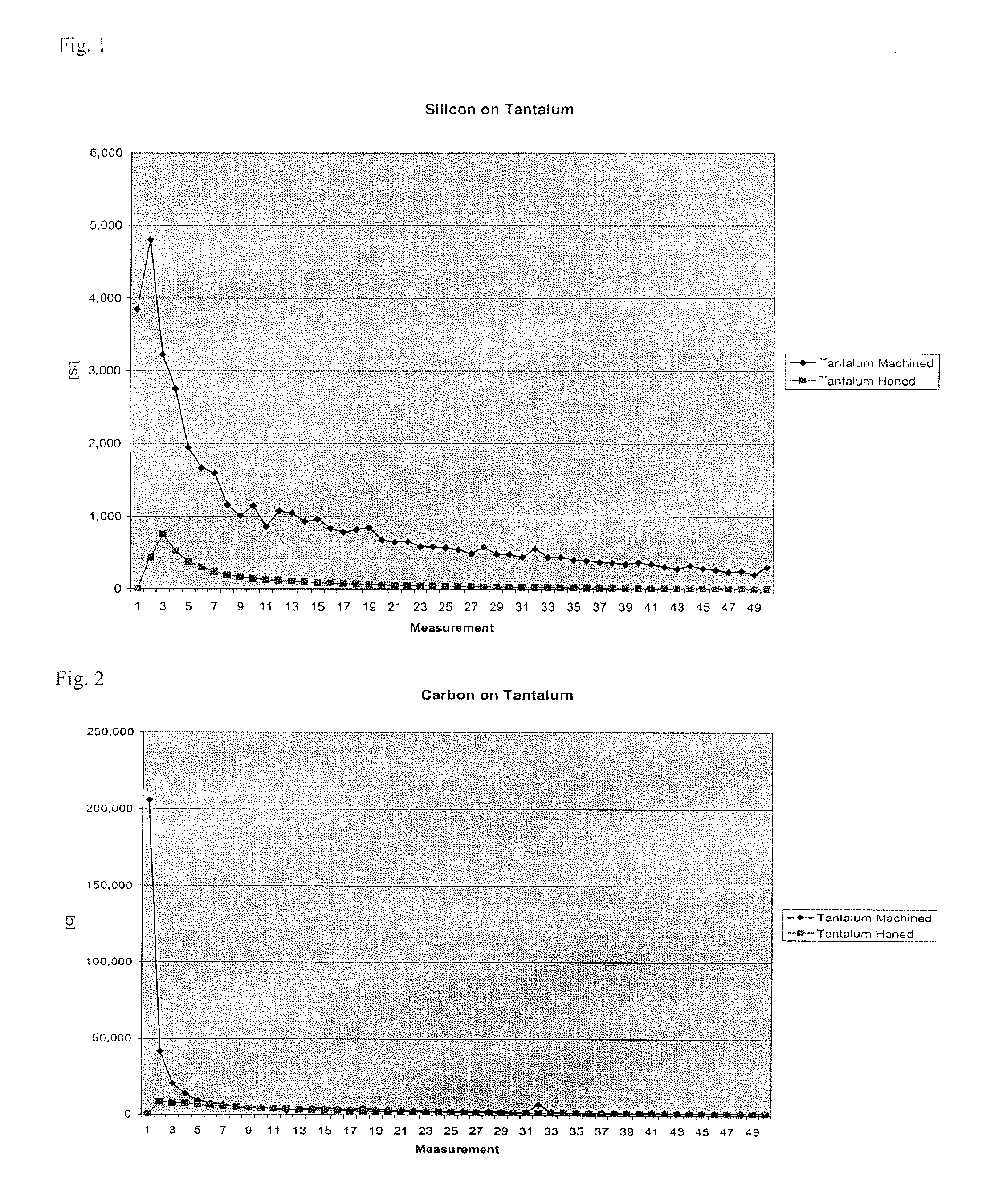
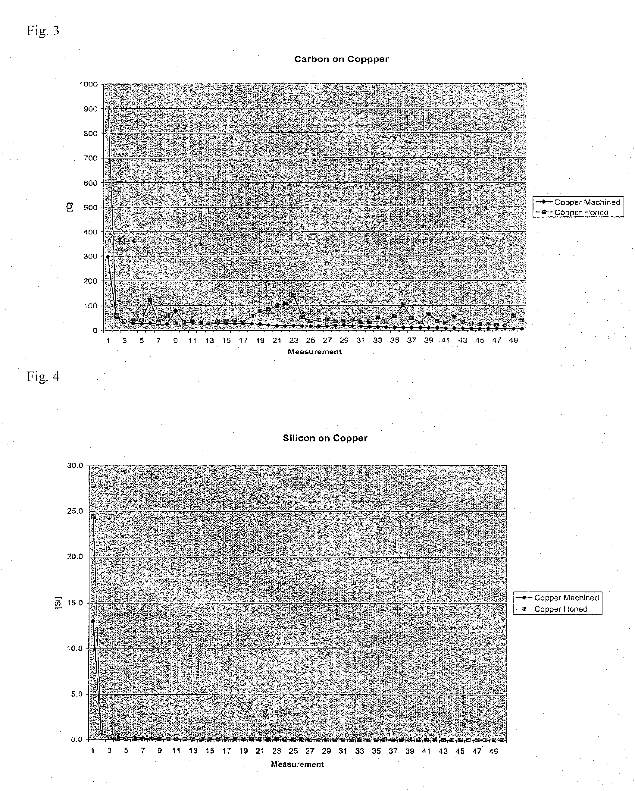
[0034]Ta, Ti, and Cu targets were subjected to XH processes in accordance with the invention and compared to similar targets that were processed via conventional methods which included machining and mechanical polishing (sanding) steps. The so-treated targets were subjected to GDMS analysis at varying target depths to analyze the presence of contaminants on the target. A round sample, approximately 1 inch in diameter was prepared and placed in a flat cell GDMS test. The sample is sputtered slowly and the atoms removed from the surface are counted as they pass through a mass spectrometer.

[0035]Results of these studies are graphically displayed in FIGS. 1-6. The X axis in each of the graphs depicts the target surface level or thickness along the surface at which the contaminants were analyzed. Th...


PUM

PropertyMeasurementUnit
Diameteraaaaaaaaaa
Surface roughnessaaaaaaaaaa
Thicknessaaaaaaaaaa

Abstract

A method is provided to remove a thickness of a sputter target surface deformation layer to thereby achieve a reduced burn-in time during sputtering operations. The method comprises extrusion hone polishing of the target surface with a visco-elastic abrasive medium.

Description

CROSS-REFERENCE TO RELATED APPLICATION[0001]This application claims the priority benefit of U.S. Provisional Patent Application No. 60 / 898,159 filed Jan. 29, 2007.FIELD OF INVENTION[0002]The invention relates to methods of improving the surface roughness (Ra) and cleanliness of a sputter target surface by removal of the target surface deformation layer. Additionally, surface contamination is minimized, including such contamination that is caused by dielectric materials. Consequently, initial sputtering performance is improved and particulate emissions during target “burn in” are minimized. The invention also pertains to targets made by such methods.BACKGROUND OF THE INVENTION[0003]Cathodic sputtering is widely used for the deposition of thin layers of material onto desired substrates. Basically, this process requires a gas ion bombardment of the target having a face formed of a desired material that is to be deposited as a thin film or layer on a substrate. Ion bombardment of the ta...

Claims


Application Information

Patent Timeline
IPC IPC(8): B24B33/055B24B33/10
CPCC23C14/3414C23C14/34
Inventor BANKS, TERRY L.SMATHERS, DAVID B.
Owner TOSOH SMD
Why Eureka
Try Eureka