Vapor-Barrier Vacuum Isolation System

a vacuum isolation and vapor barrier technology, applied in the direction of vacuum evaporation coating, electrolysis components, coatings, etc., can solve the problems of limited throughput, high cost, and large evacuation of the chamber, and achieve the effect of cost-effective and higher pressur

Inactive Publication Date: 2010-05-20
NASA
View PDF9 Cites 13 Cited by
  • Summary
  • Abstract
  • Description
  • Claims
  • Application Information

AI Technical Summary

Benefits of technology

[0007]Accordingly, a system and method as set forth herein provide a cost-effective way to enable use of higher working chamber or working environment pressures in conjunction with high power charged particle beam device while using a minimal amount of mechanical pumping. The system and method can accommodate the high vacuum and short propagation path constraints of typical charged particle beam generators that require an open aperture or orifice for the discharge of the beam. A high-vacuum beam generation chamber or vacuum chamber, e.g., the vacuum chamber or volume of an electron gun, can be directly connected to a working chamber through a series of coaxial holes, openings, or orifices, with the working chamber having a significantly higher pressure relative to that of the source or vacuum chamber. For example, the vacuum chamber can be evacuated to approximately 10−6 torr while the connected working chamber is at a pressure of approximately 1 torr, although other vacuum or pressure levels can also be used within the intended scope of the invention. The system and method thus allow a continuously operated high-power beam to be generated at a high vacuum and used in a modest pressure environment.

Problems solved by technology

That is, in order to produce or generate a collimated charged particle beam, electron and ion beam generators or sources often require moderate-to-high vacuum conditions, and thus require substantial evacuation of a chamber in which the beam generating device or source is located.
The orifice required for passage of the beam may be as large as several millimeters in diameter, a substantial opening which can represent a formidable vacuum leak in the vacuum chamber used for generating the beam.
The need to pump or evacuate the entire working volume of a large ion beam or electron beam system to such a high vacuum as noted above can entail considerable time, complexity, and related expense, and can likewise result in limited throughput.
However, this approach still requires the use of high-capacity pumps to achieve even moderate working chamber pressure levels, and with relatively small orifice diameters.
Moreover, if the working chamber pressure is sufficiently high, the pumping requirement can quickly render as impractical such a differential pumping approach.
Beam propagation for significant distances at intermediate pressures can also result in scatter, defocusing, and / or beam attenuation, which can collectively limit both the effectiveness and the utility of the collimated beam.

Method used


Image

  • Vapor-Barrier Vacuum Isolation System
  • Vapor-Barrier Vacuum Isolation System
  • Vapor-Barrier Vacuum Isolation System

Examples


Embodiment Construction

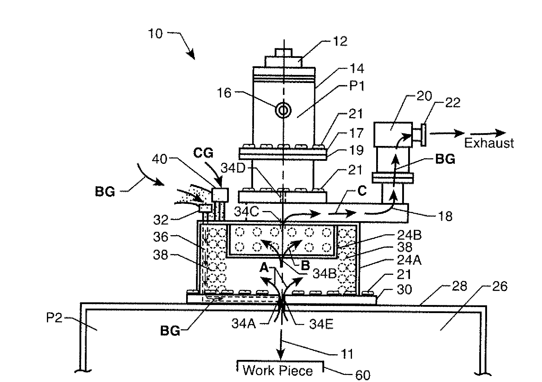
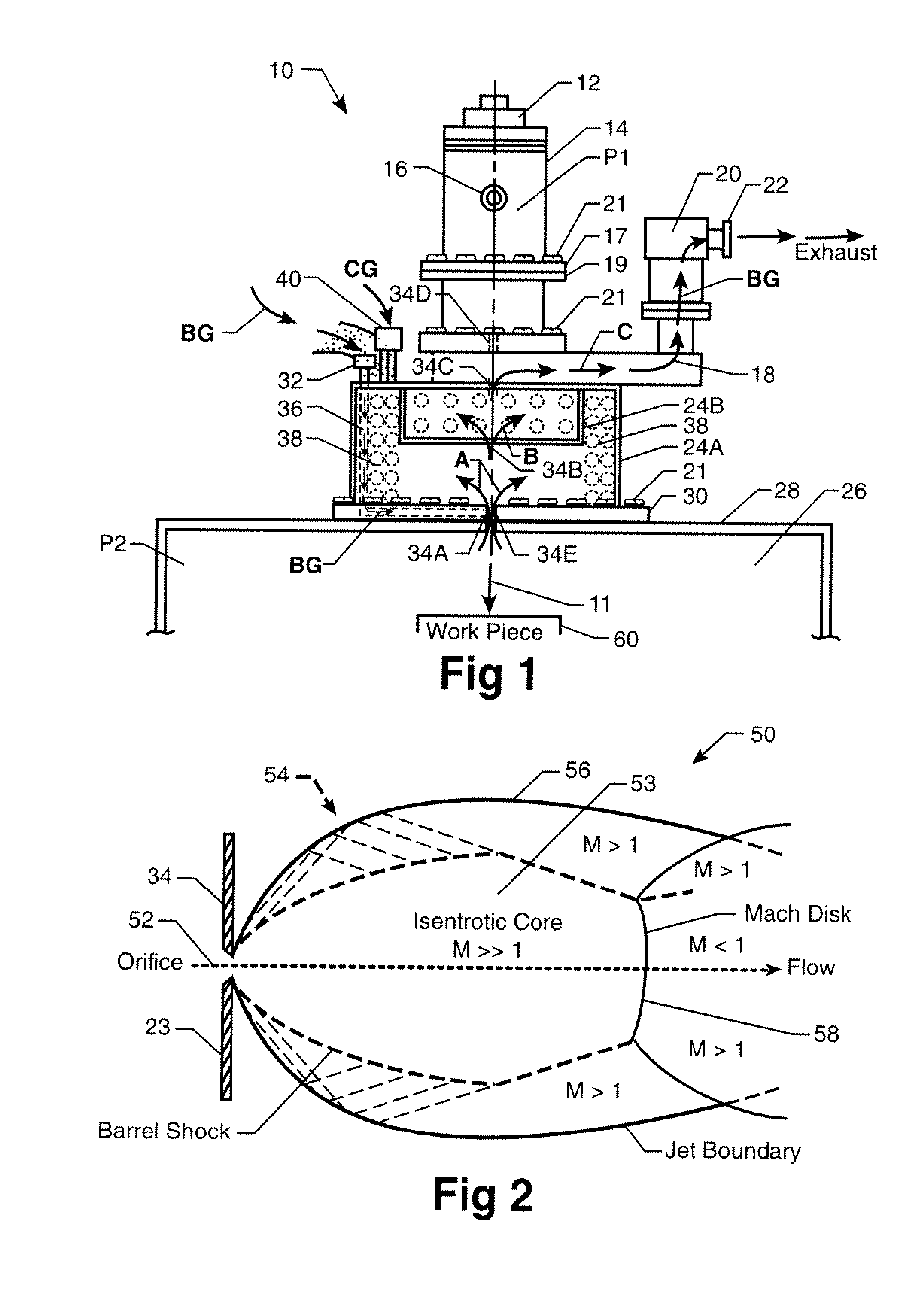
[0020]Referring to the drawings, wherein like reference numbers represent like components throughout the several figures, and beginning with FIG. 1, a multi-stage vapor barrier vacuum isolation system or VBS 10 is operable for generating and applying a highly collimated beam 11, such as an electron beam or an ion beam, for use in a low pressure environment. Exemplary applications include processes relating to electron beam freeform fabrication (EBF3) for near-net-shape manufacturing of aerospace or other alloy parts and / or components, as well as vaporizing, welding, cutting, and / or localized melting of metals.

[0021]For example, in the years ahead manned and unmanned missions to Mars are expected to become more frequent. The Martian atmosphere, which is predominantly carbon dioxide or CO2, has an average ambient pressure of approximately 7.5 millibars or 5.6 torr. Depending on the ability to adequately focus and steer an electron beam at such a pressure level in a CO2-rich environmen...


PUM

PropertyMeasurementUnit
diameteraaaaaaaaaa
diameteraaaaaaaaaa
lengthaaaaaaaaaa

Abstract

A system includes a collimated beam source within a vacuum chamber, a condensable barrier gas, cooling material, a pump, and isolation chambers cooled by the cooling material to condense the barrier gas. Pressure levels of each isolation chamber are substantially greater than in the vacuum chamber. Coaxially-aligned orifices connect a working chamber, the isolation chambers, and the vacuum chamber. The pump evacuates uncondensed barrier gas. The barrier gas blocks entry of atmospheric vapor from the working chamber into the isolation chambers, and undergoes supersonic flow expansion upon entering each isolation chamber. A method includes connecting the isolation chambers to the vacuum chamber, directing vapor to a boundary with the working chamber, and supersonically expanding the vapor as it enters the isolation chambers via the orifices. The vapor condenses in each isolation chamber using the cooling material, and uncondensed vapor is pumped out of the isolation chambers via the pump.

Description

CROSS-REFERENCE TO RELATED APPLICATIONS[0001]This application claims priority to and the benefit of U.S. Provisional Application 61 / 114,511, filed on Nov. 14, 2008, which is hereby incorporated by reference in its entirety.ORIGIN OF THE INVENTION[0002]The invention described herein was made by employees of the United States Government and may be manufactured and used by or for the Government of the United States of America for governmental purposes without the payment of any royalties thereon or therefor.TECHNICAL FIELD [0003]The present invention relates generally to high power charged particle beams such as ion beams or electron beams, and in particular to the generation of the same in a vacuum chamber for use in a connected working chamber or other working environment having a significantly greater pressure than that of the vacuum chamber.BACKGROUND OF THE INVENTION[0004]Certain collimated beams such as charged ion beams and electron beams can be used for vaporizing, cutting, wel...

Claims


Application Information

Patent Timeline
Patent Type & Authority Applications(United States)
IPC IPC(8): C23C14/34
CPCH01J37/16H01J37/18H01J2237/002H01J2237/2002H01J2237/182H01J2237/188H01J2237/006
Inventor WEINSTEIN, LEONARD M.TAMINGER, KAREN M.
Owner NASA
Why Eureka
Try Eureka