Polarizing element and method of producing the same

a technology of polarizing elements and polarizing plates, which is applied in the direction of polarizing elements, instruments, nuclear engineering, etc., can solve the problems of insufficient heat resistance or light fastness, inability to achieve ideal achromatic color polarizing plates for the entire visible spectral region, and inability to achieve polarizing elements distinctly inferior

Active Publication Date: 2010-06-03
FUJIFILM CORP
View PDF6 Cites 23 Cited by
  • Summary
  • Abstract
  • Description
  • Claims
  • Application Information

AI Technical Summary

Benefits of technology

[0014]Other and further features and advantages of the invention will appear more fully from the following description.

Problems solved by technology

However, if iodine is used for a polarizing plate, its heat resistance or light fastness is insufficient since iodine is highly sublimable.
Further, the extinction color becomes dark grayish blue, and an ideal achromatic color polarizing plate for the entire visible spectral region cannot necessarily be obtained.
However, such an organic dye has a problem such that only polarizing elements are obtainable which are distinctly inferior to those employing iodine for dichroic property.
However, this method had such a problem that a long time period and efforts are required for e.g. the stretching step.
However, it was known that there was a problem for heat resistance of the film obtained by the method by Dreyer.
Thus, there are many cases that even the conventional dyes that can be employed for the polarizing elements passing through the above-mentioned stretching treatment are not suitable for the wet film-forming method.
However, although such materials are suitable for the process, they have had such a drawback that they cannot show high dichroism.
However, when an anisotropic dye film is obtained by combining the several kinds of dichroic dyes each other, a molecular alignment for mixing different molecules is disturbed and there was a problem that achieving a high dichroism is difficult.

Method used


Image

  • Polarizing element and method of producing the same
  • Polarizing element and method of producing the same
  • Polarizing element and method of producing the same

Examples


example 1

Preparation of a Transparent Resin Cured Layer Coating Liquid A

[0301]The following composition was poured into a mixing tank, followed by stirring, to prepare a transparent resin cured layer coating liquid A.

[0302]To 7.5 mass parts of trimethylolpropanetriacrylate (trade name: Viscoat #295, manufactured by Osaka Organic Chemical Industry Ltd.), 2.7 mass parts of poly(glycidyl methacrylate) with mass average molecular weight 15,000, 7.3 mass parts of methyl ethyl ketone, 5.0 mass parts of cyclohexanone and 0.5 mass parts of a photopolymeraiztion initiator (trade name: Irugacure 184, Ciba Specialty Chemicals, Inc.) were added, and the mixture was stirred. The resultant mixture was subjected to filtration using a polypropylene filter with hole diameter 0.4 μm, to prepare a hard coat layer coating liquid A.

Preparation of a Transparent Resin Cured Layer Coating Liquid B

[0303]A coating liquid B containing a disk-like liquid crystalline compound having the following composition was prepare...

example 2

[0309]To 9.8 mass parts of chloroform, were added 0.096 mass parts of a dichroic azo dye No. (A-46), 0.096 mass parts of a polyfunctional monomer, ethylene oxide-modified trimethylolpropanetriacrylate (trade name: V#360, manufactured by Osaka Organic Chemical Industry Ltd.), and 0.008 mass parts of Irugacure OXE-01 (trade name, manufactured by Ciba Speciality Chemicals, Inc) as a polymerization initiator, and the mixture was stirred and dissolved. The resultant mixture was subjected to filtration to obtain a dichroic dye composition coating liquid. Then, the above coating liquid was applied to the above polyvinyl alcohol alignment film which was formed on a glass substrate and rubbed, and the film was dried under the air at room temperature to remove chloroform. Thereafter, the state of alignment of the film was fixed by irradiating the film with ultraviolet rays of intensity 5 J under a nitrogen atmosphere (concentration of oxygen: 100 ppm or less). In succession, the above transpa...

reference example 1

[0311]A polarizing element was prepared in the similar manner as in Example 1, except that the transparent resin cured layer was not provided to laminate. The dichroic ratio (D) and the pencil hardness of the resultant light polarizing element are shown in Table 1. The composition had nematic mesomorphism, and a high dichroic ratio (light absorption anisotropic property) sufficiently functional as a polarizing element. However, the pencil hardness of the polarizing element was 2B or softer, showing that the physical strength was not enough for a polarizing element.

TABLE 1Azo dyePhase transitionDichroicPencilNo.No.Phase transition temperaturetemperature of compositionratiohardnessExample 1A-46K 158° C. N 240° C. IN 150° C. I23HExample 2A-46K 158° C. N 240° C. IN 150° C. I23HReferenceA-46K 158° C. N 240° C. IN 150° C. I232B or softerExample 1K: Crystalline PhaseN: Nematic PhaseI: Isotropic Phase


PUM

PropertyMeasurementUnit
thicknessaaaaaaaaaa
thicknessaaaaaaaaaa
thicknessaaaaaaaaaa

Abstract

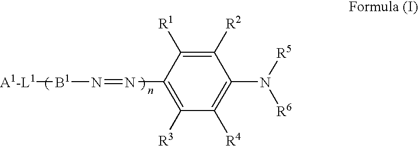
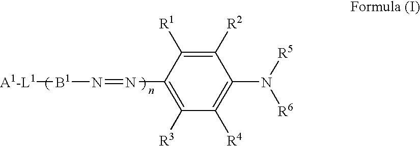
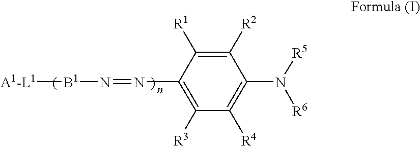
A polarizing element, containing: a transparent support; a light absorption anisotropic layer formed of a dichroic dye composition; and a transparent resin cured layer, with the layers being laminated in this order on the support, and with the composition containing at least one dichroic dye of formula (I) which has nematic mesomorphism but containing no liquid crystalline achromatic compound:
    • wherein R1 to R4 are a hydrogen atom or a substituent; R5 and R6 are a hydrogen atom or an alkyl group; L1 represents —N═N—, —CH═N—, —N═CH—, —C(═O)O—, —OC(═O)— or —CH═CH—; A1 represents a phenyl, naphthyl or aromatic heterocyclic group; B1 represents a divalent aromatic hydrocarbon or divalent aromatic heterocyclic group; and n is an integer from 1 to 5.

Description

FIELD OF THE INVENTION[0001]The present invention relates to a polarizing element containing a dichroic azo dye, and to a method of producing the same. Further, the present invention relates to a liquid crystal display device having the polarizing element.BACKGROUND OF THE INVENTION[0002]When a function such as an attenuation function, a polarization function, a scattering function and a light-shielding function is required to effect for an irradiated light including a laser light and a natural light employed, hitherto, an apparatus or device which operates based on a different principle was adapted depending on the function required. Accordingly, products corresponding to the functions were prepared respectively by production processes that were different depending on the respective functions.[0003]For example, in LCD (liquid crystal display), linear polarizing plates or circular polarizing plates are used to control optical rotation or birefringence in display. Also in OLED (organ...

Claims


Application Information

Patent Timeline
Patent Type & Authority Applications(United States)
IPC IPC(8): G02F1/1335G02B5/30G02B1/08C09K19/00B05D3/06
CPCC09K19/22C09K19/24C09K19/3444C09K19/3497C09K19/601Y10T428/10G02F1/133528G02F2202/04G02F2203/04Y10T428/1041G02B5/3025C09K2323/00C09K2323/031
Inventor MORISHIMA, SHINICHIUTAGAWA, ERI
Owner FUJIFILM CORP
Why Eureka
Try Eureka