Memory device and storage apparatus

a memory device and storage device technology, applied in the field of memory devices and storage devices, can solve the problems of difficult to reduce the size of the device, difficult to maintain the characteristics of the above-mentioned nonvolatile memory, and increase the manufacturing cost of the dram, so as to improve the yield rate, the effect of inexpensive manufacturing and inexpensive storage apparatus

Inactive Publication Date: 2010-06-03
SONY CORP
View PDF21 Cites 10 Cited by
  • Summary
  • Abstract
  • Description
  • Claims
  • Application Information

AI Technical Summary

Benefits of technology

[0027]It is other object of the present invention to provide a memory device having an arrangement which can easily be manufactured by a relatively simple manufacturing method.
[0072]Also, in particular, even when the thin film whose resistance value is sufficiently lower than that of the memory thin film is sandwiched between the memory thin film of the memory device and the electrode, it is possible to suppress the influence exerted upon the change of the resistance value due to the rise of temperature. Thus, similarly as described above, even when the memory device is used under high temperature circumstance or even when data is stored in the memory device for a long period of time, the memory device can be maintained in the high resistance state stably. Therefore, since the information recorded on the memory thin film can be held stably, it becomes possible to make the memory device become highly-reliable.

Problems solved by technology

However, since the DRAM is complex in manufacturing process as compared with ordinary logic circuit (large scale integrated circuit (LSI circuit)) and a signal processing circuit, it is unavoidable that the manufacturing cost of the DRAM increases.
However, the above-mentioned nonvolatile memories become difficult to maintain characteristics of memory devices as the memory device comprising each memory cell is being reduced in size.
As a consequently, it is difficult to reduce the device in size up to the limit of a design rule and up to the limit of a manufacturing process.
However, the above-mentioned memory device having the structure in which any one of the upper electrode or the lower electrode contains Ag, Cu, Zn and in which the GeSe amorphous chalcogenide material is sandwiched by these electrodes encounters with the problem in which the aforementioned ion conductor whose resistance is changes is promoted to be crystallized by causes such as the rise of temperature in the manufacturing process, the rise of temperature generated by Joule heat of a recording current, a heat load over a long period of time in which data is stored during a long period of time so that the ion conductor is wholly or partly crystallized, thereby changing the original electric characteristics such as the change of the resistance value of the memory device and the change of recording / erasing operation voltage.
Then, when the crystal material is used as the recording material between the upper and lower electrodes, for example, as compared with the case in which the amorphous material is used as the above-mentioned recording material between the upper and lower electrodes, this memory device encounters with many problems and it is difficult to mass-produce this memory device inexpensively.
Also, in order to obtain crystallinity of excellent quality, a high-temperature treatment at 700° C. should be carried out, and there arises a problem in which characteristics of an MOS transistor that has been formed in advance are deteriorated by heat.
Further, in order to enable the crystal to grow, the material of the underlayer is limited and hence a single crystal material should be used.

Method used


Image

  • Memory device and storage apparatus
  • Memory device and storage apparatus
  • Memory device and storage apparatus

Examples


Embodiment Construction

[0131]The present invention will now be described in detail with reference to the drawings.

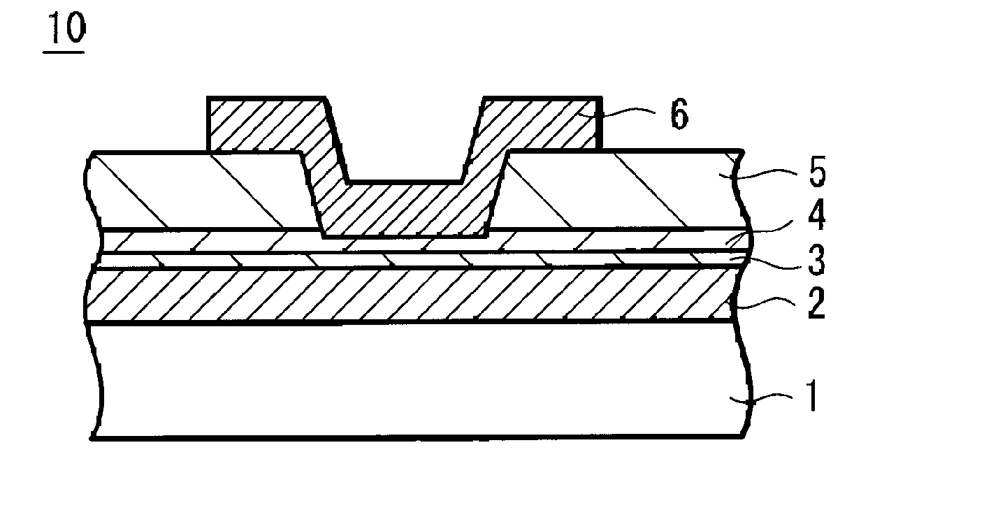
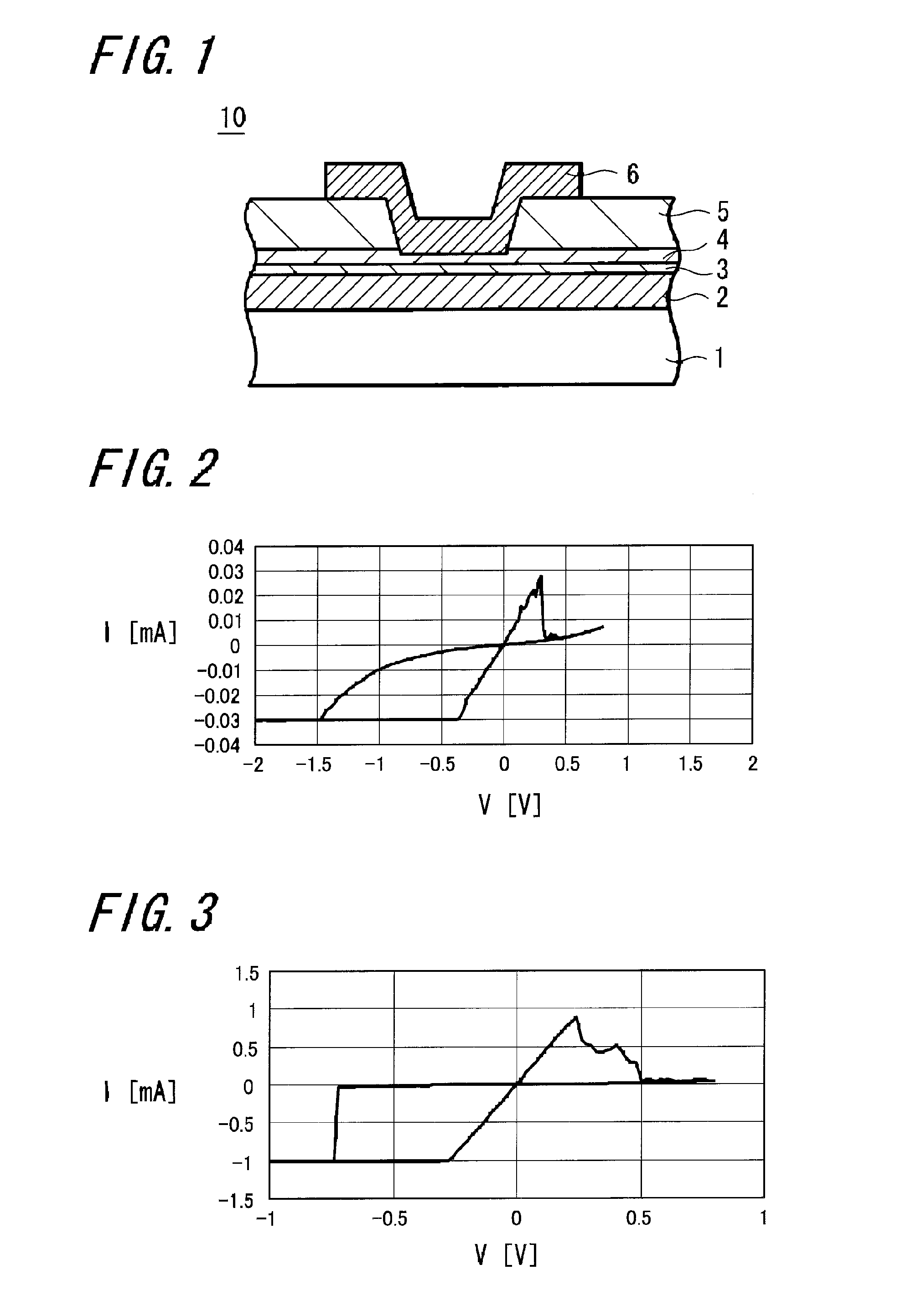
[0132]FIG. 1 of the accompanying drawings is a schematic diagram (cross-sectional view) showing an arrangement of a memory device according to an embodiment of the present invention.

[0133]As shown in FIG. 1, a memory device 10 includes a substrate 1 with a high electric conductivity, for example, a (P++) silicon substrate 1 which is heavily doped with P-type impurities and on which a lower electrode 2 is formed. This lower electrode 2 has formed thereon a layer 3 containing Cu, Ag, Zn on which a memory thin film 4 is formed. An upper electrode 6 is connected to the memory thin film 4 through a through-hole formed on an insulating layer 5 on this memory thin film 4.

[0134]The lower electrode 2 can be made of interconnection materials for use with the semiconductor process, for example, TiW, Ti, W, WN, Cu, Al, Mo, Ta, silicide and the like.

[0135]When the lower electrode 2 is made of a TiW film, f...


PUM


Abstract

A memory device 10 has an arrangement in which a memory thin film 4 is sandwiched between first and second electrodes 2 and 6, the memory thin film 6 contains at least rare earth elements, the memory thin film 4 or a layer 3 in contact with the memory thin film 4 contains any one of elements selected from Cu, Ag, Zn and the memory thin film 4 or the layer 3 in contact with the memory thin film 4 contains any one of elements selected from Te, S, Se. The memory device can record and read information with ease stably, and this memory device can be manufactured easily by a relatively simple manufacturing method.

Description

RELATED APPLICATION DATA[0001]This application is a division of U.S. patent application Ser. No. 10 / 991,075, filed Nov. 17, 2004, the entirety of which is incorporated herein by reference to the extent permitted by law. The present application claims the benefit of priority to Japanese Patent Application Nos. 2003-400319 filed Nov. 28, 2003, 2003-415412 filed Dec. 12, 2003, and 2004-182775 filed Jun. 21, 2004, the entirety of which all are incorporated by reference herein to the extent permitted by law.BACKGROUND OF THE INVENTION[0002]1. Field of the Invention[0003]The present invention relates to a memory device capable of recording information and a storage apparatus using such a memory device.[0004]2. Description of the Related Art[0005]In information equipment such as computers, a high-density DRAM (dynamic RAM (random-access memory)) which can be operated at high speed is widely used as a random-access memory.[0006]However, since the DRAM is complex in manufacturing process as ...

Claims


Application Information

Patent Timeline
Patent Type & Authority Applications(United States)
IPC IPC(8): G11C17/00H01L45/00H01L29/18H01L27/105G11C11/00G11C13/02H01L21/105H01L21/8247H01L27/10H01L27/115H01L27/24
CPCG11C13/0007H01L45/1625G11C2213/11G11C2213/15G11C2213/33G11C2213/34G11C2213/56G11C2213/72H01L27/2409H01L27/2436H01L45/085H01L45/1233H01L45/1266H01L45/143H01L45/144H01L45/145H01L45/146G11C13/0011H10B63/20H10B63/30H10N70/245H10N70/8416H10N70/8825H10N70/883H10N70/026H10N70/8828H10N70/8833H10N70/826G11C13/00H10N70/8822H10N70/046
Inventor ARATANI, KATSUHISAMAESAKA, AKIHIROKOUCHIYAMA, AKIRATSUSHIMA, TOMOHITO
Owner SONY CORP
Why Eureka
Try Eureka