Process for upgrading coal pyrolysis oils

a technology of pyrolysis oil and catalyst, which is applied in the direction of hydrocarbon oil cracking, hydrocarbon oil treatment, liquid hydrocarbon mixture production, etc., can solve the problems of limited utility of crude oil from the wellhead, less easy handling and transportation of coal than fluidic, and low utilization rate of coal pyrolysis oil, so as to reduce the requirement of makeup catalysts and improve catalyst utilization.

Active Publication Date: 2010-06-17
MACARTHUR JAMES B +2
View PDF13 Cites 60 Cited by
  • Summary
  • Abstract
  • Description
  • Claims
  • Application Information

AI Technical Summary

Benefits of technology

[0034]The pyrolysis oil is fed with hydrogen to a multi-stage ebullated-bed reactor (operating as hydrotreater and hydrocracker) containing an appropriate catalyst to first stabilize the feed at low temperature and is then fed to downstream reactor(s), containing an appropriate catalyst, operated at higher temperatures to further treat and hydrocrack the pyrolysis oils to a more valuable synthetic crude oil or to finished distillate products. The relatively high heat of reaction is used to provide the energy necessary to increase the temperature of each reactor stage thus eliminating or reducing the need for additional external heat input. A refined heavy oil product stream can be recycled to the coal pyrolysis oil to minimize feedstock fouling of heat exchangers and feed heaters.General Description of the Invention
[0044]In the refinery scheme, this process allows to enhance the value of streams which are generally burned or treated as wastes; in fact the present process may also process additional feedstocks along with the coal pyrolysis oils, for example one or more streams selected from a group consisting of: FCC slurry oil, phenolics, FCC light cycle oil, decant oil, anthracene oil, coke oven oils, petroleum derived pyrolysis oils, and steam cracker tars; such stream is combined with the coal pyrolysis oil and is processed with the hydrogen stream in step a).
[0054]It is advantageous that the combined stream from step b) is first processed in an interstage separator prior to step c) to remove heteroatom gases (H2O, H2S, NH3, CO2), light hydrocarbon gases, and to provide a lower volumetric liquid feedstock for stage two. Generally, additional hydrogen is fed to the ebullated-bed reactor of step c).

Problems solved by technology

However, coal has three major drawbacks: (1) Coal is a solid and is less easily handled and transported than fluidic or gaseous materials; (2) Coal contains compounds which, upon burning, produce “air toxics” and the pollutants associated with acid rain; and (3) Coal is not a uniform fuel product, varying in characteristics from region to region and from mine to mine.
Crude oil from the wellhead has limited utility.
Raw coal, as it is mined, also has limited utility being used mostly for direct combustion to produce heat and steam to generate electricity.
High sulfur bituminous coals and high moisture subbituminous coals are very different raw materials and cannot be interchanged as fuels.
Vast deposits of coal also exist in Eastern Europe, Russia, and China but are either far away from manufacturing regions or contain high levels of pollutants relative to the heating value of the coal.
However, after World War II, crude oil was widely available at reasonable prices and commercial coal liquefaction was therefore not commercially attractive.
As a result, very little liquid fuels sold today are produced using a coal liquefaction process.
While commercially demonstrated, the ICL technologies are very complex, capital intensive, and have low thermal efficiencies compared to direct coal liquefaction.
The coal pyrolysis tars are unstable and viscous making filtration difficult.
The DCL technologies demonstrated commercial readiness, however, no commercial projects proceeded as oil prices fell and oil supplies increased.
These coal pyrolysis oils are highly aromatic, olefinic, unstable, and contain objectionable sulfur, nitrogen, and oxygen contaminants, and may contain coal solids which will plug fixed-bed reactors.

Method used


Image

  • Process for upgrading coal pyrolysis oils
  • Process for upgrading coal pyrolysis oils

Examples


example 1

[0063]Table 2 below shows the performance of the process using a typical coal pyrolysis oil with two different (single and two-stage) process configurations.

[0064]Case 1 is the pre-invention configuration which utilizes a single stage ebullated-bed reactor system.

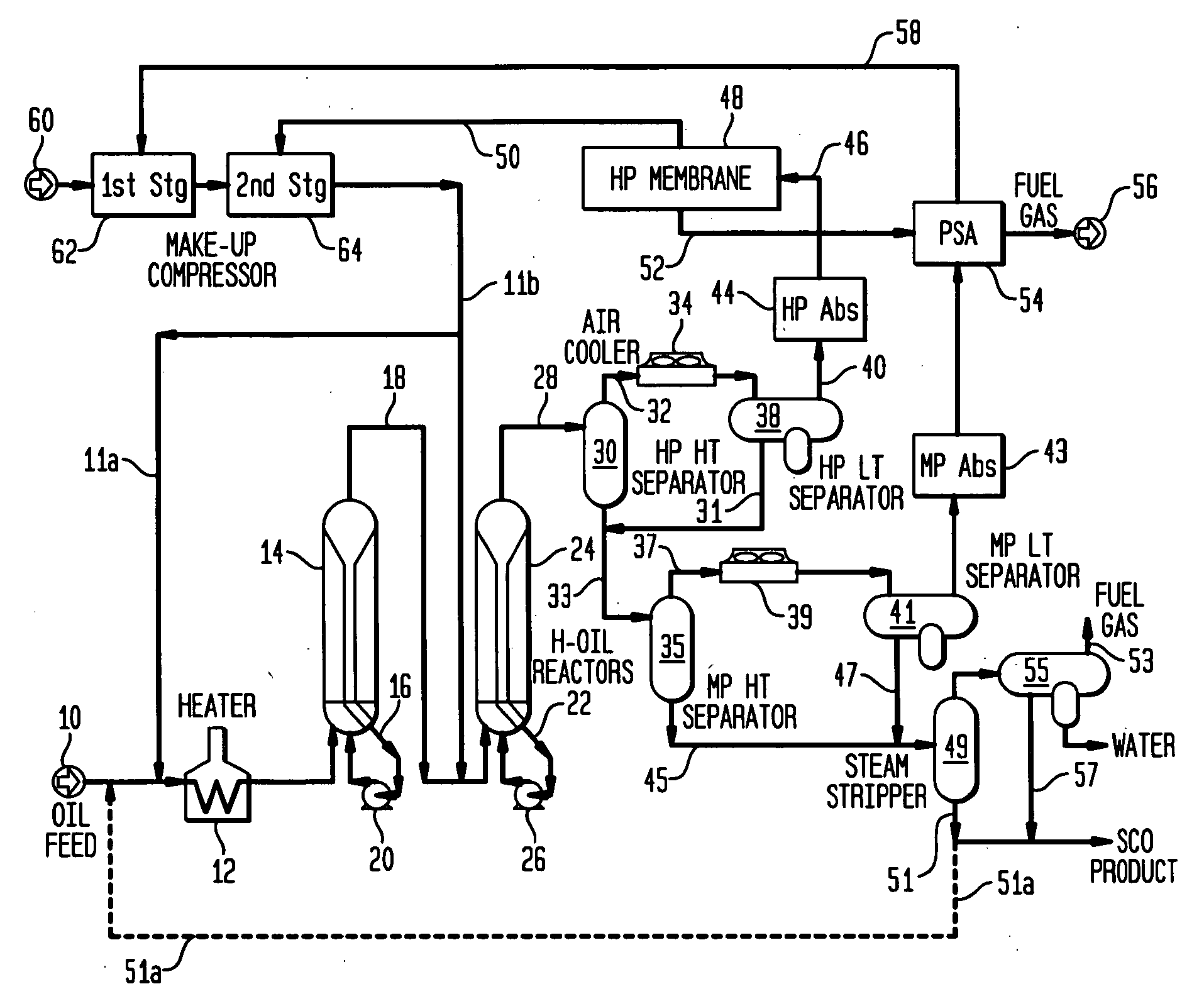
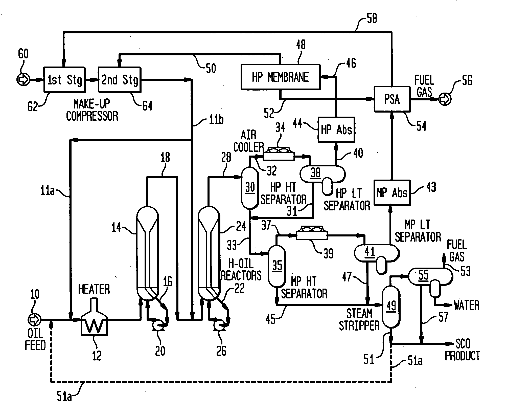
[0065]Case 2 illustrates the performance of the current invention utilizing a two-stage ebullated-bed reactor system with optimized operating conditions.

[0066]Utilizing the same amount of reactor volume, the processing configuration of the current invention results in higher conversion, heteroatom removal and improved product quality.

TABLE 2Invention PerformanceCoal Pyrolysis -FEEDSTOCKOil CFeed Gravity, °API4.3Feed Gravity, S.G.1.042Hydrogen, W %8.9Nitrogen, W %0.6Sulfur, W %0.3Oxygen, W %7.8Boiling Range343° C.−43343° C.+57Case12Operating ConditionsNumber of Stages12Type of ReactorEbullated-BedEbullated-BedLHSV, hr−10.40.4Reactor Temp., ° C.427400 / 438H2PP, bar124124Performance440° C.+ Resid77.583.4Conversion, V %HDS93.098...


PUM

PropertyMeasurementUnit
sizeaaaaaaaaaa
wt %aaaaaaaaaa
wt %aaaaaaaaaa

Abstract

This invention utilizes a novel method and set of operating conditions to efficiently and economically process a potentially very fouling hydrocarbon feedstock. A multi-stage catalytic process for the upgrading of coal pyrolysis oils is developed. Coal Pyrolysis Oils are highly aromatic, olefinic, unstable, contain objectionable sulfur, nitrogen, and oxygen contaminants, and,may contain coal solids which will plug fixed-bed reactors. The pyrolysis oil is fed with hydrogen to a multi-stage ebullated-bed hydrotreater and hydrocracker containing a hydrogenation or hydrocracking catalyst to first stabilize the feed at low temperature and is then fed to downstream reactor(s) at higher temperatures to further treat and hydrocrack the pyrolysis oils to a more valuable syncrude or to finished distillate products. The relatively high heat of reaction is used to provide the energy necessary to increase the temperature of the subsequent stage thus eliminating the need for additional external heat input. A refined heavy oil product stream is recycled to the fresh feed to minimize feedstock fouling of heat exchangers and feed heaters.

Description

BACKGROUND OF THE INVENTION[0001]1. Field of the Invention[0002]This invention relates to a multi-stage catalytic process for upgrading coal pyrolysis oils with the objective of producing valuable gasoline, jet fuel, and diesel fuel. Coal Pyrolysis Oils are highly aromatic, olefinic, and are unstable. Additionally, they contain objectionable sulfur, nitrogen, and oxygen contaminants, and may also contain coal solids that would plug fixed-bed reactors.[0003]2. Description of Prior Art[0004]Coal is the world's most abundant fossil fuel. However, coal has three major drawbacks: (1) Coal is a solid and is less easily handled and transported than fluidic or gaseous materials; (2) Coal contains compounds which, upon burning, produce “air toxics” and the pollutants associated with acid rain; and (3) Coal is not a uniform fuel product, varying in characteristics from region to region and from mine to mine. In fossil fuels, the ratio of hydrogen atoms to carbon atoms is most important in det...

Claims


Application Information

Patent Timeline
Patent Type & Authority Applications(United States)
IPC IPC(8): C10G45/20
CPCC10G1/002C10G65/04C10G65/06C10G65/12C10G2300/4081C10G2300/1044C10G2300/107C10G2300/202C10G2300/301C10G2300/1022
Inventor MACARTHUR, JAMES B.COLYAR, JAMES J.DUDDY, JOHN E.
Owner MACARTHUR JAMES B
Why Eureka
Try Eureka